 |
Blender Materials: Diffusion |
|
Introduction
In Blender, materials are used to paint the surface of objects, to create an environment, or to suggest special effects. Blender offers many options. The most recent is managed by a concept named Cycles Render.
In this exercise, we will review some of the techniques used to create and manade materials.
 Practical Learning: Starting the Project
- Start Blender
- In the Tools window, click the Create tab
- In the Create tab of the Tools window, click Plane
- In the Properties window, click the Object button

- To change the name of the shape, in the Properties window, click Plane to select its name
- Type Back Wall and press Enter
- In the Transform section, change the following values:
Location - Y: -2
           Y:  6
           Z: 4.95
Rotation - X: 90
Scale    - X: 8
           Y: 5
- To add a new plane, in the Create tab of the Tools window, click Plane
- While the plane is still selected, in the Properties window, change the following values:
Name       Left Wall
Location - X: -8
           Z:  5
Rotation - Y: 90
Scale    - X: 5
           Y: 8
- To add a new plane, on the menu below the work area, click Add -> Mesh -> Plane
- While the plane is still selected, in the Properties window, change the following values
Name:      Floor
Location - Z: .1
Scale    - X: 8.5
           Y: 10
- Zoom in to get a better view of the scene. Here is an example:

- Position the mouse in the work area and press Shift + A -> Mesh -> Cylinder
- In the Add Cylinder section below the Tools window, change the following values
Vertices:  8
Radius:   .065
Depth:     6
Location - Z: 8.5

- In the Tools window, click the Create tab if necessary and click Cylinder
- In the Add Cylinder section below the Tools window, change the following values
Vertices:   5
Radius:    .65
Depth:     .25
Location - Z: 5.65
- In the Properties window, change the name to Ceiling Fan and press Enter
- While the hexagon is selected, position the mouse in the work area, press M and, in the Layers window, click the second box
- On the menu bar of the 3D View, in the Visible Layers section, click the second button
- Zoom in to see as much as possible of the hexagon:

- Press Tab to display in Edit Mode
- On the menu bar of the 3D-View, click the Face Select button

- Right-click one of the vertical faces to select it
- Press I to create an inset on the selected face
- Type .05 and press Enter:

- Using the same technique, create an inset on each vertical face:

- By pressing and holding Shift while right-clicking, select each of the inside faces you had created to select all of them:


- On the menu bar of the 3D View, click the Pivot button and select Individual Origins:

- Zoom out to display the hexagon far from you
- Press E to extrude
- Type 1.5

- Press Enter
- While the faces are still selected, press S to change their sizes
- Type .75 and press Enter:

- Press R to rotate
- Type -30 and press Enter:

- Press Tab to return to the Object Mode
- Zoom out to see less of the ceiling fan
- Press M and, in the Layers window, click the first button
- On the menu bar of the 3D View, in the Visible Layers section, click the first button:

Introduction to Creating a Material
There are various ways to create a material. Cycles Render is a technique used to create materials with various options. To use Cycles Render, in the top menu bar of blender, change the combo box from Blender Render to Cycles Render.
The most fundamental technique is to first select the desired object in the work area. Then, in the Properties window, click the Material button. In the group of panels, click Add Node. There are other techniques we will review.
To assist you in managing materials, Blender provides various categories or groups of objects. A shader is the most fundamental technique used to create the appearance of an object. It can simply consist of painting an object with a certain color. It can consist of combining colors. It can consist of logically or illogically creating some type of appearance.
To distinguish them, each shader has a name. In the Properties window, the name of a shader appears in the Surface text box or combo box. That control also provides one of the ways to select a shader.
Practical Learning: Using Cycles Render
- On the top menu bar, click Blender Render and, in the menu that appears, select Cycles Render
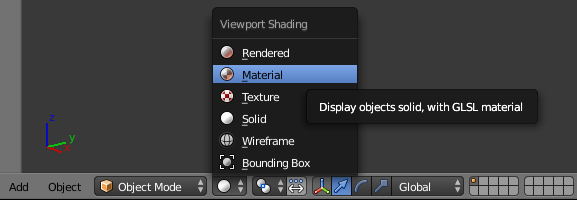
- On the menu bar of the 3D View, click the Viewport Shading button and select Material:
- In the Properties window, click the Render button

- In the Resolution section, click 50%, type 100 and press Enter
Diffusing a Color
As mentioned earlier, the most fundamental material in Blender is called Diffuse BSDF. At a minimum, it is used to paint a surface with a color. For this reason, its most fundamental characteristic is its Color option, which you can set as we have seen previously. The roughness of a material is the ability to notice some details on its surface. To support this, the Diffuse BSDF material is equipped with a property named Roughness. Its value can be set between 0.0 and 1.00 (if you set a value above 1.00, the rendering engine would consider the value to be 1.00). In most cases, the lower the value, the closer the object appears to the color that was set. The higher the value, the darker the object would appear but still as close as possible to the color that was set.
In this exercise, we will continue to experiment with different ways to start a material and apply to the surface of an object.
Practical Learning: Starting a Material
- In the Outliner, click Floor
- In the Properties window, click the Material button

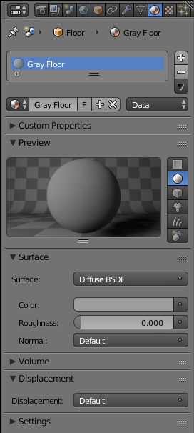
- In the Material section of the Properties window, click the New button
- Click Material.001, type Gray Floor and press Enter
- Click the Preview button to expand it
- Notice that the Surface type is set to Diffuse BSDF.
Click the Color button
- Click somewhere in the vertical bar to get a gray color (I am using R = G = B = 0.338):

- Right-click the left border of the Properties window and click Split Area:
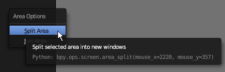
- Position the mouse somewhere between the top border and the center of the work area
- Click to confirm. If necessary, resize the windows
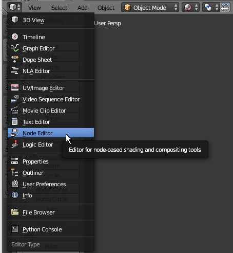
- In the bottom-left side of the new window, click the 3D Viewport button and select Node Editor
- In the Outliner, click Ceiling Fan
- In the Node Editor, click the New Button
- Zoom in the Node Editor to see the material window as much as possible
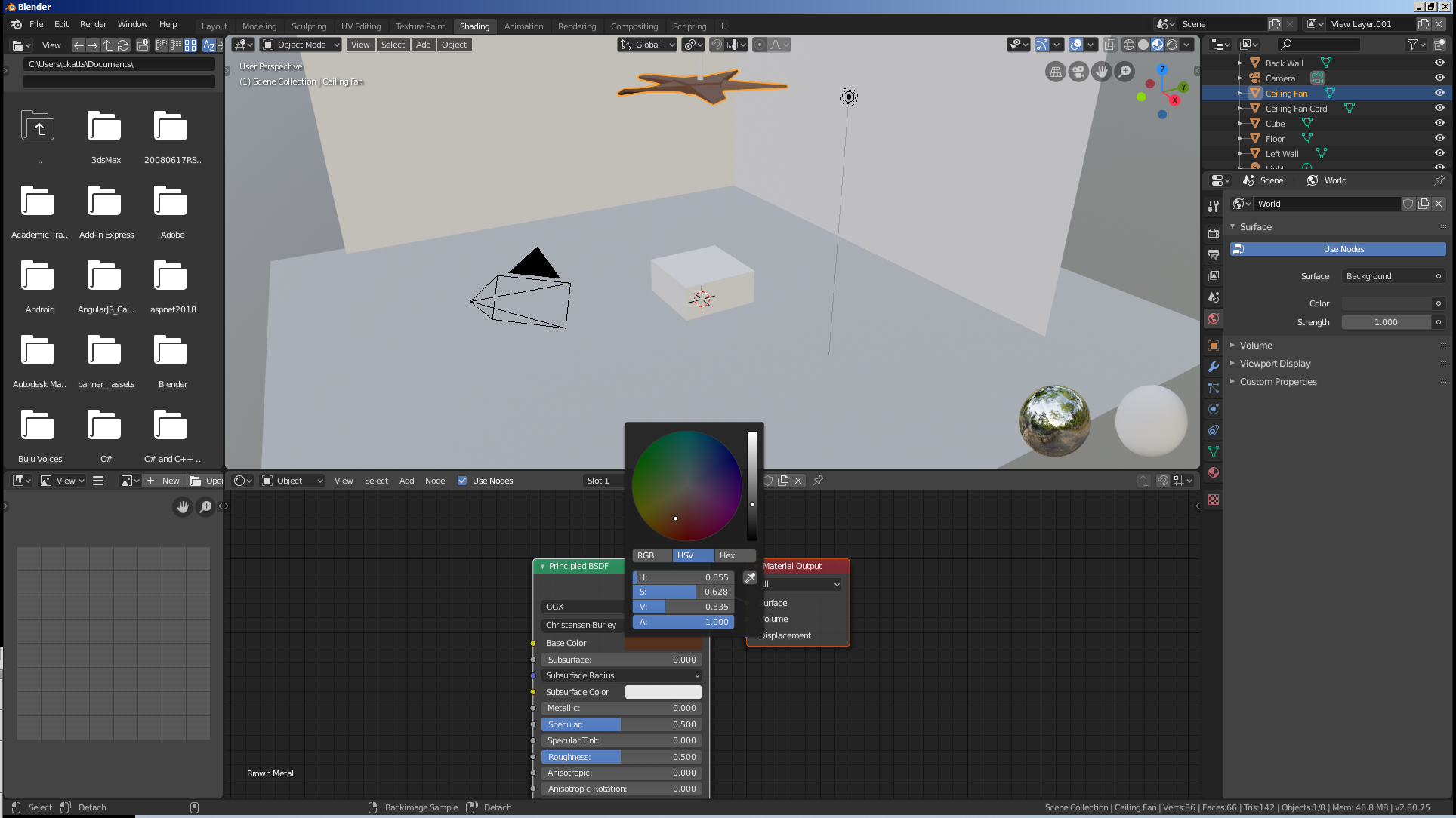
- On the Node Editor menu bar, click Material.001, type Brown Metal and press Enter to change the name of the material
- In the Properties window, click the Color button
- Click its HSV button and set the color as:
H: .055
S: .628
V: .335
- In the work area, right-click the wall on the left side (alternatively, in the Outliner, click Left Wall) to select it
- In the Material section of the Properties window, click the New button
- Double-click Material.001, type Blue Paint and press Enter
- Notice that the Surface type is set to Diffuse BSDF.
In the Node Editor, zoom in and, in the Diffuse window, click the Color button
- Click RGB
- Set the following values:
R: .445
G: .625
B: .95

- In the Diffuse BSDF window, set the Roughness to .8

- In the work area, click the right wall (alternatively, in the Outliner, click Back Wall)
- On the menu under the Node Editor, click the button on the left side of New and select Blue Paint
- In the work area, right-click the tiny cylinder above the lamp to select it
- In the Properties window, click the button on the left side of New:

- Click Brown Metal
- Right-click the border between the Node Editor and the 3D-View
- Click Join Area
- Position the mouse in the Node Editor and click (or click the up-pointing arrow)
- In the Numeric Pad, press 0 to display the camera view
- Press N to display the Properties Region
- In the Properties Region, click Lock Camera to View
- Use the buttons on the mouse and the keyboard to get a better view. Here is an example:

- In the Properties region, click Lock Camera to View
- Press N to close the Properties region
- On the main menu, click Render -> Render Image

- After viewing the results, press Esc