 |
Blender Materials: Input Objects |
|
Introduction
In Blender, every material has at least one characteristic. One common characteristic is the color applied to an object. Some other characteristics use numbers or else. Many of the characteristics can be set directly in the Material section of the Properties window. Here is an example:
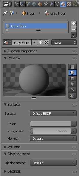
In the same way, a characteristic can be set in the Node Editor. Here is an example:
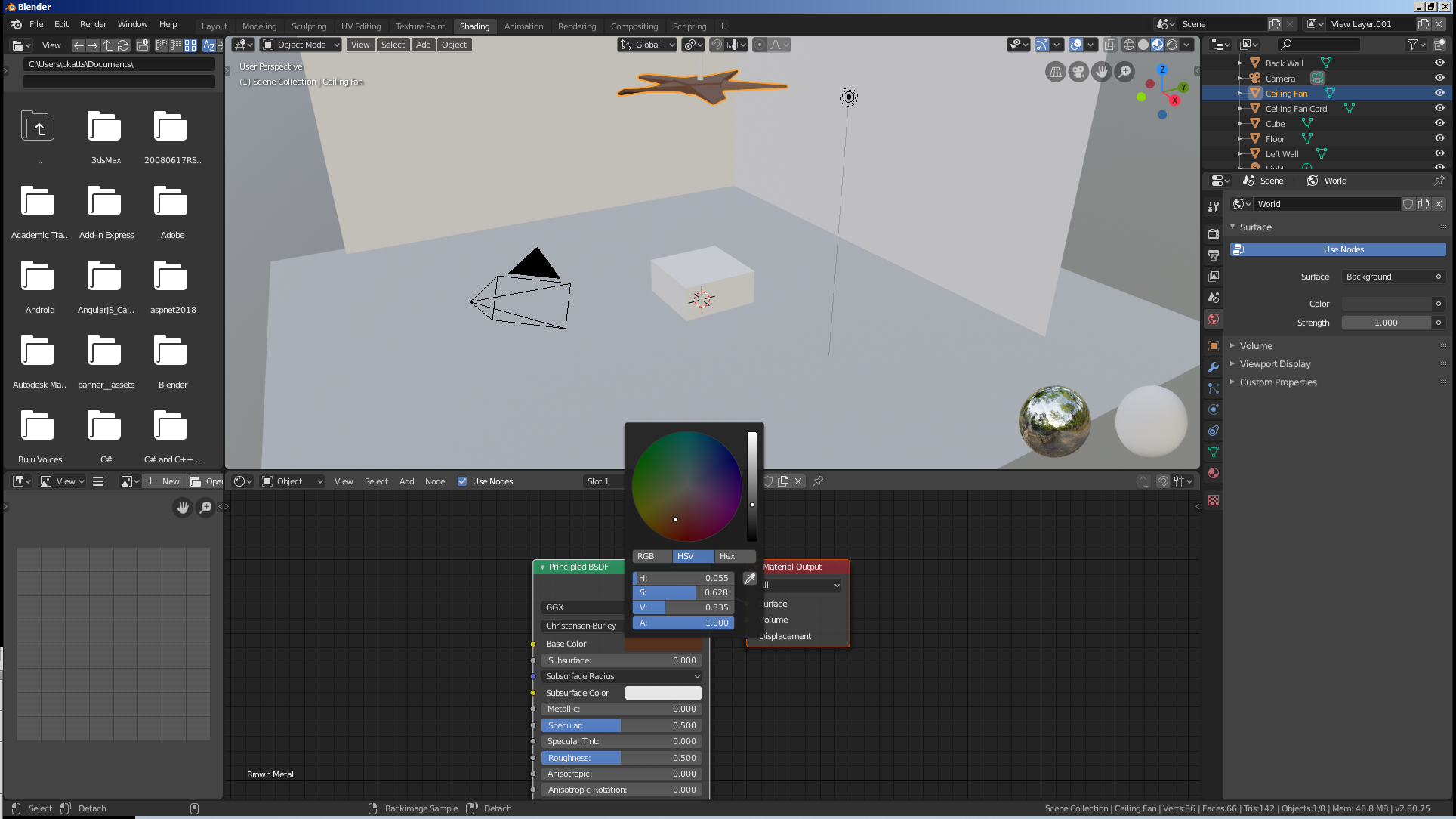
To support better flexibility and/or more details in specifying a characteristic or value of a material, Blender provides the ability to add an input to a material.
 Practical Learning: Starting the Project
- Start Blender
- In the Properties window, click the Object button

- The default cube on the scene should be selected (if you have doubt, right-click it to select it).
In the Outliner, click the Restrict Viewport Visibility button (the eye) of Cube to hide it
 Practical Learning: Creating a Regular Hill
- In the Tools window, click Create
- In the Create tab of the Tools window, click Plane
- In the Object tab of the Properties window, click Plane to select the name
- Type Oversight and press Enter
- In the Transform section of the Properties window, change the following values:
Location - X: -20
			 Y: 32.5
		     Z: -.03
Scale    - X: 7
	         Y: 7
- On the menu bar of the 3D View, click Object Mode and click Edit Mode
- Position the mouse in the work area and press W
- In the menu that appears, click Subdivide
- In the Subdivide section below the Tools window, set the Number of Cuts to 23
- On the menu bar of the 3D View, make sure the Vertex Select option is selected.
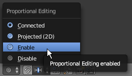
Still on the menu bar of the 3D Viiew, click the Proportional Editing button 
- On the Menu that appears, click Enable
- On the plane, right-click the central vertex or one of the middle vertices
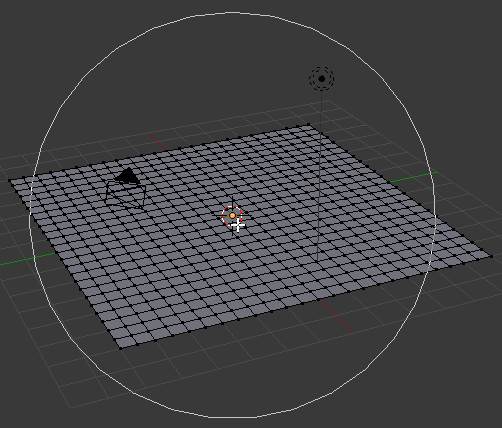
- Press G to set the size of the move
- Roll the mouse wheel from outside towards you 19 times or until the circle appears as follows:
- Press Z to move the top vertically
- Type 10 and press Enter:
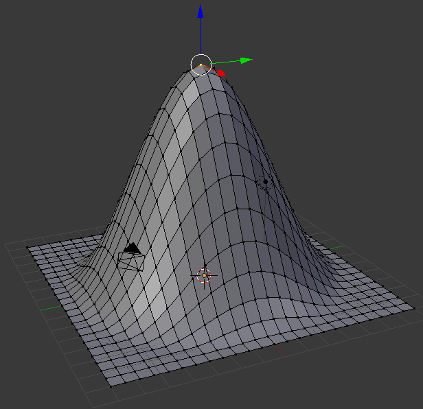
- On the menu bar of the 3D View, click the Proportional Editing button and click Disable
- On the menu bar of the 3D View, click Edit Mode and click Object Mode
- Position the mouse in the work area, press Shift + D to copy the hill and press Enter
- In the Object tab of the Properties window, change the following values:
Name:      Provincial
Location - X: -32
		     Y: 20
		     Z: -.1
Scale    - X: 20
		     Z:.4
- In the Outliner, click Oversight to select it
- Position the mouse in the work area, press Shift + D and press Enter
- In the Object tab of the Properties window, change the following values:
Name:        Cake Off
Location   - X: -35
		       Y: 10
		       Z: -.1
Rotation   - Z: 30
Scale      - X: 15
		       Y: 7.5
             Z: .25
- In the Outliner, click Oversight to select it
- Position the mouse in the work area, press Shift + D and press Enter
- In the Object tab of the Properties window, change the following values:
Name:      April Fish
Location - X: -40
		     Y: 2
		     Z: -.3
Scale    - X: 6
		     Y: 6
           Z: .2
- In the Outliner, click Oversight to select it
- Position the mouse in the work area, press Shift + D and press Enter
- In the Object tab of the Properties window, change the following values:
Name:      Facial Works
Location - X: -10
		     Y: 30
		     Z: -.03
Scale    - X: 5
		     Y: 5
           Z: .5
- In the Outliner, click Oversight to select it
- Position the mouse in the work area, press Shift + D and press Enter
- In the Object tab of the Properties window, change the following values:
Name:      Pitcher
Location - X: -5
		     Y: 38
		     Z: -.03
Scale    - X: 8
		     Y: 8
           Z: .65
- In the Outliner, click Oversight to select it
- Position the mouse in the work area, press Shift + D and press Enter
- In the Object tab of the Properties window, change the following values:
Name:      Half Tail
Location - X: 8
		     Y: 35
		     Z: -.01
Rotation - Z: -30
Scale    - X: 10
		     Y: 10
           Z: .5
- In the Outliner, click Oversight to select it
- Position the mouse in the work area, press Shift + D and press Enter
- In the Object tab of the Properties window, change the following values:
Name:      Ascension
Location - X: 16.5
		     Y: 40
		     Z: -.03
Scale    - X: 5
		     Y: 5
           Z: .25
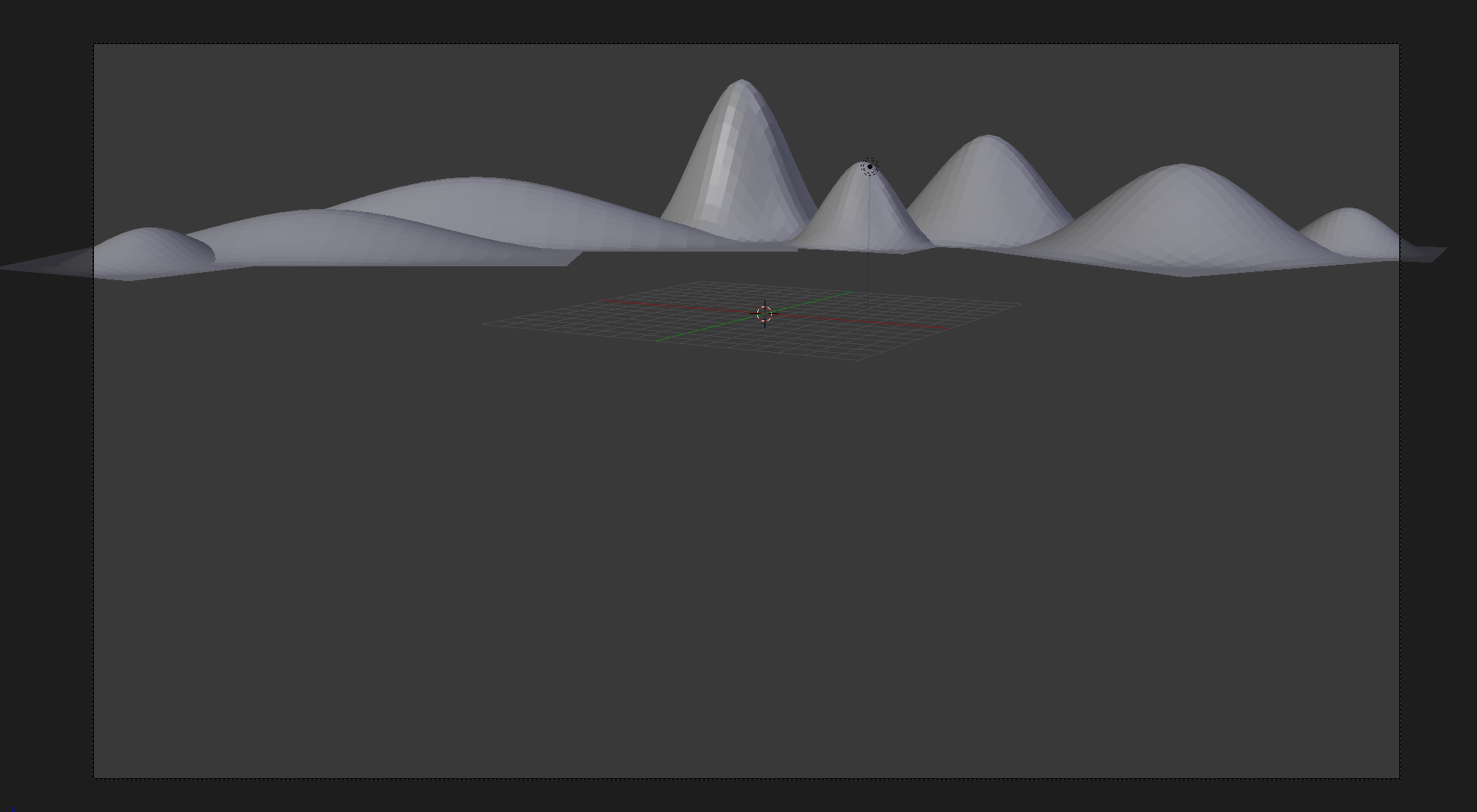
- In the Outliner, click the Restricted Viewport Visibility button (the eye) on the right side of Ascension to hide it
- In the Outliner, click the Restricted Viewport Visibility button on the right side of Half Tail to hide it
- In the Outliner, click the Restricted Viewport Visibility button on the right side of Pitcher to hide it
- In the Outliner, click the Restricted Viewport Visibility button on the right side of Facial Works to hide it
- In the Outliner, click the Restricted Viewport Visibility button on the right side of April Fish to hide it
- In the Outliner, click the Restricted Viewport Visibility button on the right side of Cake Off to hide it
- In the Outliner, click the Restricted Viewport Visibility button on the right side of Provincial to hide it
- In the Outliner, click the Restricted Viewport Visibility button on the right side of Oversight to hide it
 Practical Learning: Modeling a Tree
- On the Tools window, click Create
- In the Create tab of the Tools window, click Cone
- In the Add Cylinder section of the Tools window, change the following values:
Vertices:   6
Radius 1:  .2
Radius 2:  .15
Depth:     1
Location - X: 0
			 Y: -25
           Z: .45
Rotation - X: 5
		     Y: 5
           Z: 90
- In the Object tab of the Properties, click Cone to select the name
- Type Classic Tree and press Enter
- On the menu bar of the 3D View, click Object Mode and click Edit Mode
- Zoom in to see as much as possible of the cylinder and, on the menu bar of the 3D-View, click the Face Select button

- Move the view so you can see the top face and right-click that top face to select it:
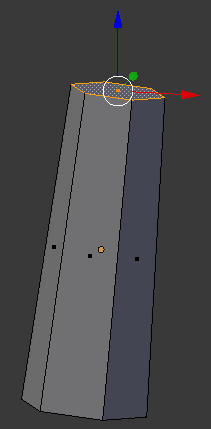
- In the Numeric Pad, press 1 to access the front view
- Press R to rotate the selected face
- Press Y to rotate horizontally
- Type -15 and press Enter
- Press E to extrude
- Type .75 and press Enter
- Press S to resize the face
- Type .75 and press Enter:

- In the Numeric Pad, press 3 to access the right view
- Press G to move the face
- Press Y to move horizonotally
- Type -.15 and press Enter:

- Press R to rotate the selected face
- Press X to rotate horizontally
- Type 15 and press Enter:

- In the Numeric Pad, press 1 to display the front view:

- Press E to extrude
- Type .75 and press Enter
- Press G to move the face
- Press Y to move it horizontally
- Type .25 and press Enter
- Press G to move the face
- Press X to move it horizontally
- Type .25 and press Enter
- Press S to resize the face
- Type .75 and press Enter:

In the Numeric Pad, press 3 to access the right view:
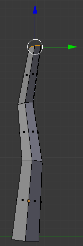
- Press R to rotate the face
- Press X to rotate horizontally
- Type -5 and press Enter
- In the Numeric Pad, press 1 to access the front view:

- Press E to extrude
- Type 1 and press Enter
- Press S to resize the face
- Type .25 and press Enter

- In the Numeric Pad, press 3 to display the right view:

- In the Numeric Pad, press 1 to access the front view
- Press Ctrl +R and get a cut as the third edge from bottom
- Click twice to confirm:

- On the Numeric Pad, press 3 to access the right side
- On the menu bar of the 3D-View, click the Face Select button

- Right-click the right side below the newly-created cut:

- Press E to extrude the face
- Type .5 and press Enter:
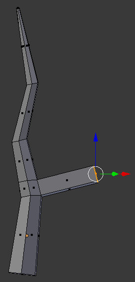
- Press G to move the face
- Press Z to move it vertically
- Type .5 and press Enter
- Press S to resize the face
- Type .5 and press Enter:
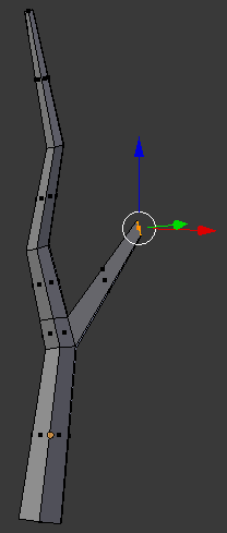
- Press E to extrude
- Type 1 and press Enter
- Press S to resize the face
- Type .35 and press Enter:
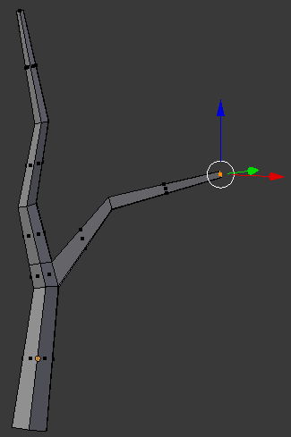
- Press Ctrl + R to create a cut in the current branch:
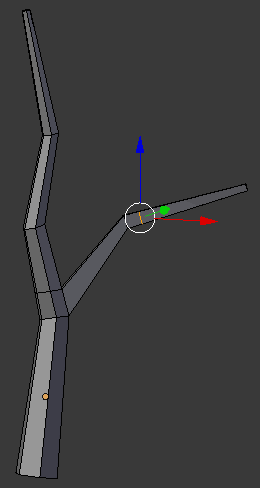
- On the menu bar of the 3D-View, click the Face Select button

- Move the view so see the top side and right-click the top face in the cut
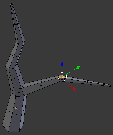
- Press E to extrude
- Type .75 and press Enter:
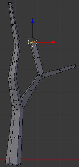
- Press G to move the face
- Press Y to move it vertically
- Type .75 and press Enter
- Press G to move the face
- Press X to move it vertically
- Type .3 and press Enter
- Press S to resize
- Type .5 and press Enter:
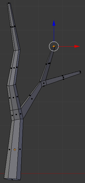
- Use Ctrl + R to create a cut above the second from top:
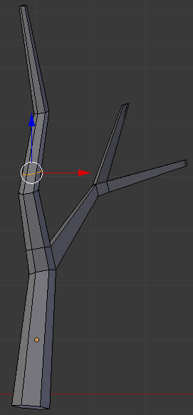
- On the menu bar of the 3D-View, click the Face Select button

- Right-click the face on the left side below the newly-created cut:
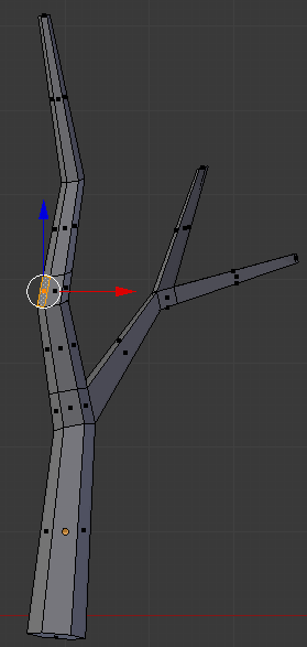
- Press E to extrude the face
- Type 1.25 and press Enter:
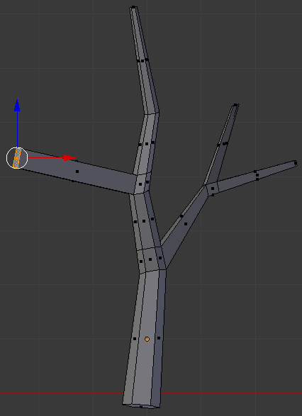
- Press G to move the face
- Press Z to move the face vertically
- Type .5 and press enter
- Press S to resize
- Type .25 and press Enter:
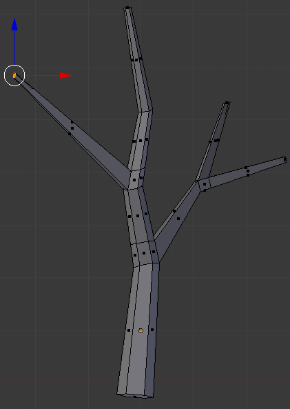
- Press Press Ctrl + R and create a cut as follows:
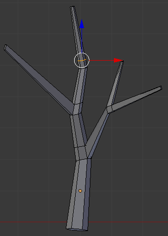
- On the menu bar of the 3D-View, click the Face Select button

- In the Numeric Pad, press 3 to access te right view
- Right-click the face on the right side below the newly-created cut:
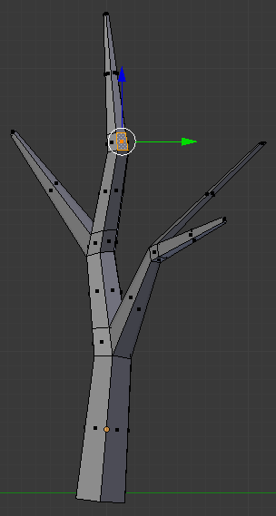
- Press E to extrude
- Type .75 and press Enter
- Press G to move the face
- Press Z to move it vertically
- Type .75 and press Enter
- Press S to resize the face
- Type .35 and press Enter:
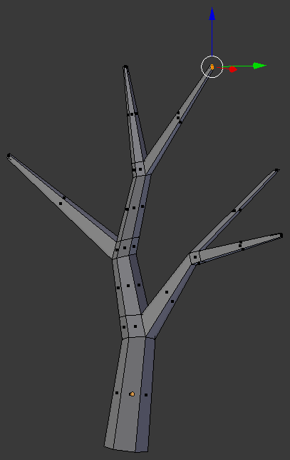
- On the menu bar of the 3D-View, click Edit Mode and click Object Mode:
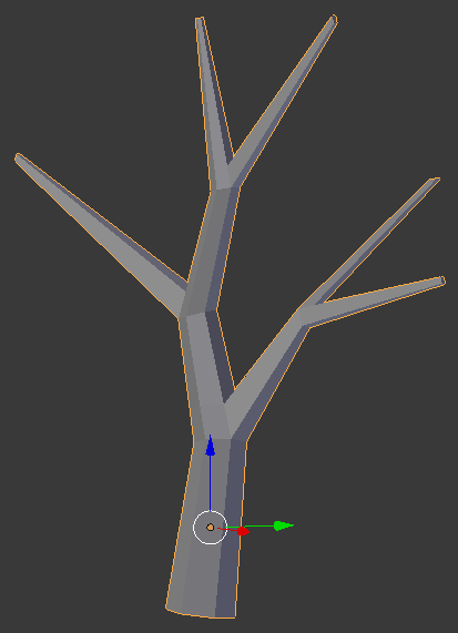
- In the Object tab of the Properties window, click Cone to select the name
- Type Oak Mali and press Enter
- In the Create tab of the Tools window, click Ico Sphere
- In the Object tab of hte Properties window, change the following values:
Name:      Eau Claire
Location - X: -.2
		     Y: -26.85
           Z: 3
Scale    - X: .75
		     Y: 1.25
           Z: .75
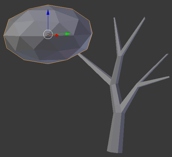
- In the Create tab of the Tools window, click Ico Sphere
- In the Object tab of hte Properties window, change the following values:
Name:      Summer Stretch
Location - X: -.75
		     Y: -24.65
           Z: 4.2
Scale    - X: 1
		     Y: 2
           Z: 1
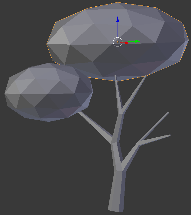
- In the Create tab of the Tools window, click Ico Sphere
- In the Object tab of hte Properties window, change the following values:
Name:      High Hope
Location - X: .85
		     Y: -24.35
           Z: 4
Scale    - X: 1.25
		     Y: .75
           Z: .75
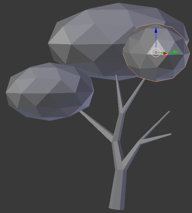
- In the Create tab of the Tools window, click Ico Sphere
- In the Object tab of hte Properties window, changethe following values:
Location - X: .3
		     Y: -23.75
           Z: 2.75
Scale    - X: .75
		     Y: 1
           Z: .75
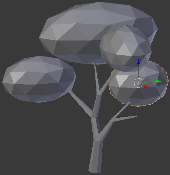
- In the Create tab of the Tools window, click Ico Sphere
- In the Object tab of hte Properties window, changethe following values:
Location - X: 2
		     Y: -23.65
           Z: 2.165
Scale    - X: 1
		     Y: 1
           Z: .75
- The above numbers are simple indications.Otherwise, adjust the branches isze, and the leaves locations and sizes until you are satisfied. Here is an example:
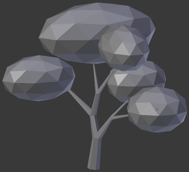
 Practical Learning: Creating the First Part of a Tree
- In the Outliner, click the Restrict Viewport Visibility button of Cube to display it
- In the Outliner, click Cube to select it
- In the Object tab of the Properties window, change the following values:
Name:      Double-Tree
Location - X: 7
		     Y: 2
           Z: .1
Scale    - X: .1
		     Y: .1
           Z: .15
- On the menu bar of the 3D View, click Object Mode and click Edit Mode
- Press Ctrl + R and get a vertical line on the Z and Y axes
- Click twice to accept the cut:
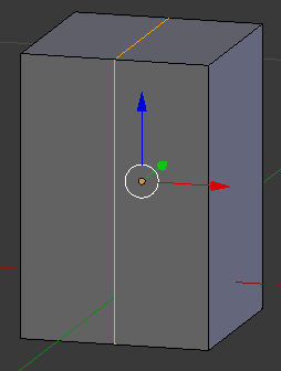
- On the menu bar of the 3D-View, click the Edge Select button

- Right-click the top edge to select it
- Press S to resize the line
- Press Y to resize along that axis
- Type .75 and press Enter:
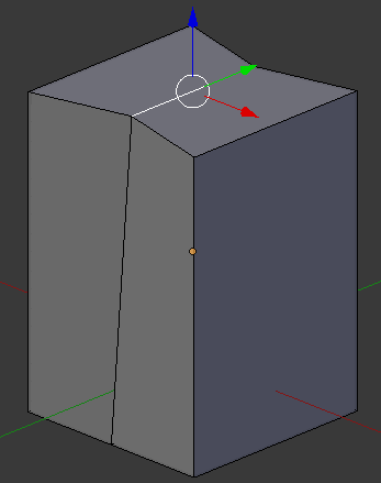
- While the top edge is still selected, press G to move it
- Press Z to move it up
- Type .02 and press Enter:
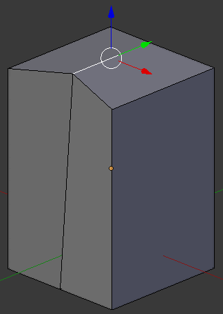
- Press Ctrl + R and get a line perpendicular to the top one
- Click twice to confirm:
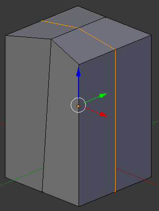
- While the line is still selected, press S to resize the shape
- Press X to resize along that axis
- Type 1.25 and press Enter:
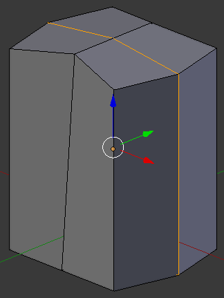
- On the menu bar of the 3D-View, click the Face Select button

- Right-click one of the top-right faces
- Press and hold Shift
- Right-click the other top-right face:
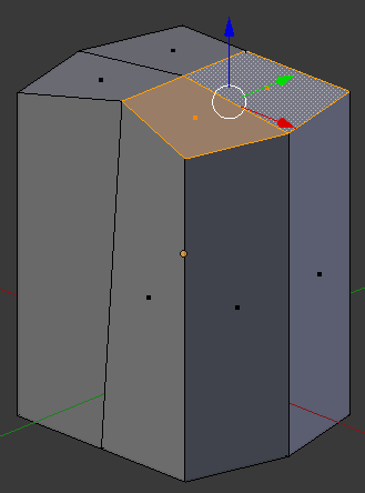
- Press E to extrude
- Type .5 and press Enter
- On the menu bar of the 3D-View, click the Vertex Select button

- Right-click the middle-back vertex:
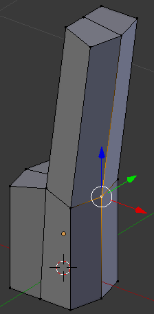
- Press G to move it
- Press X to move in that axis
- Type .01 and press Enter
- Right-click the interior vertex betwnn the top two faces:
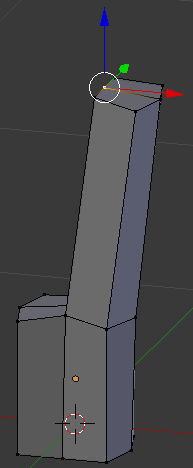
- Press G to move the vertex
- Press X to move horizontally
- Type -.02 and press Enter
- Right-click one of the vertices on the other side
- Press and hold Shilft
- Right-click the vertex on the other side
- Release Shift:
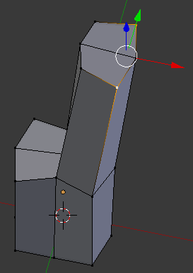
- Press S to resize
- Type .75 and press Enter:
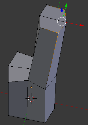
- On the menu bar of the 3D-View, click the Face Select button

- Right-click one of the top faces
- Press and hold Shift
- Right-click the other top face:
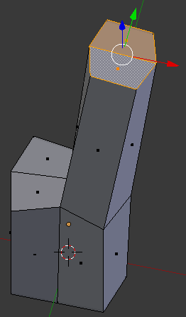
- Press S to resize the face
- Type .75 and press Enter
- On the menu bar of the 3D-View, click the Edge Select button

- Right-click the top-central edge to select it
- Press G to move the edge
- Press Z to move it vertically
- Type .01 and press Enter:
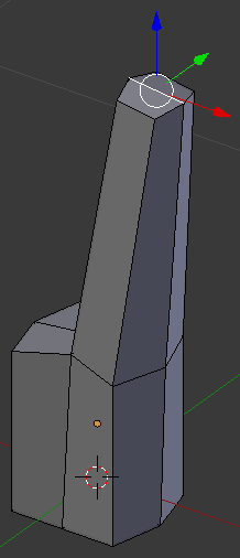
- On the menu bar of the 3D-View, click the Face Select button

- Right-click the top face behind the origin on the Y axis:
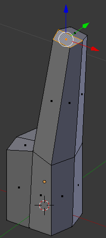
- Press E to extrude
- Type .35 and press Enter
- On the menu bar of the 3D-View, click the Edge Select button

- Right-click the inside edge:
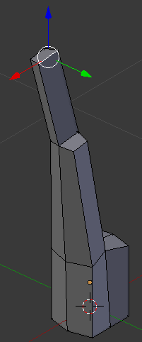
- Press S to resise the edge
- Type .75 and press Enter
- On the menu bar of the 3D-View, click the Face Select button

- Right-click the top face:
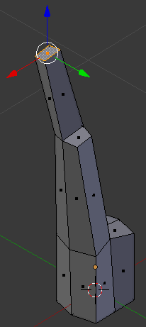
- Press S to resize the face
- Type .95 and press Enter
- Press G to move the face
- Press X to move along that axis
- Typpe .2 and press Enter
- Press R to rotate the face
- Press Y to rotate around that axis
- Type 45 and press Enter:
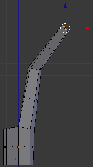
- Press Ctrl + R and get a vertical cut
- Click twice to confirm:
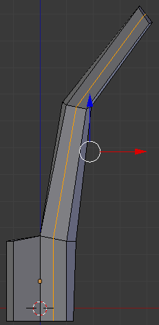
- On the menu bar of the 3D-View, click the Vertex Select button

- Right-click the bottom-outside vertex of the newly create cut:
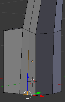
- Press G to move the edge
- Press Y to move them along that axis
- Type -.04 and press Enter
- Right-click the vertex above the one you had previously used:
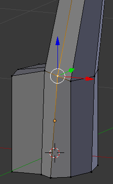
- Press G to move the edge
- Press Y to move them along that axis
- Type -.03 and press Enter
- Right-click the vertex above the one you had previously used:
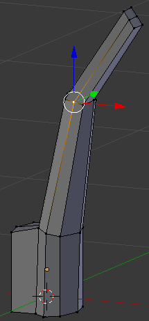
- Press G to move the edge
- Press Y to move them along that axis
- Type -.02 and press Enter
- Right-click the vertex above the one you had previously used:
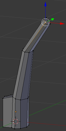
- Press G to move the edges
- Press Y to move them along that axis
- Type -.02 and press Enter
- On the menu bar of the 3D-View, click the Face Select button

- Right-click the bottom face of the top two faces:
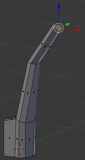
- Press E to extrude
- Type .5 and press Enter
- Press G to move the face
- Press Z to move vertically
- Type -.2 and press Enter
- Press S to resize it
- Type .5 and press Enter:
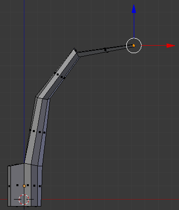
- Press G to move the face
- Press Y to move vertically
- Type -.15 and press Enter
- Move the object and right-click the face that was previously left
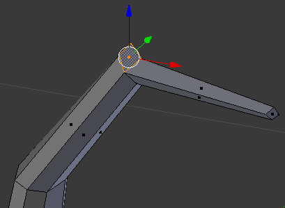
- Press E to extrude
- Type .75 and press Enter
- Press S to resize it
- Type .5 and press Enter:
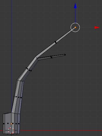
- Move the object around and select the two second faces that were left:
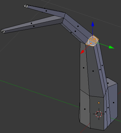
- Press E to extrude
- Type .5 and press Enter
- Press G to move the faces
- Press X to move horizontally
- Type .075 and press Enter
- Press S to resize it
- Type .75 and press Enter:
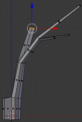
- Move the object around and right-click the right face to select it:

- Press E to extrude
- Type .55 and press Enter
- Press G to move the faces
- Press X to move horizontally
- Type .2 and press Enter
- Press S to resize it
- Type .5 and press Enter:
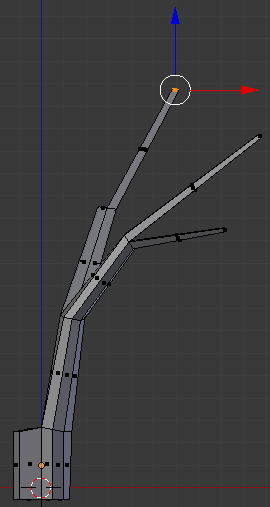
- Move the object around and select the face that was left:
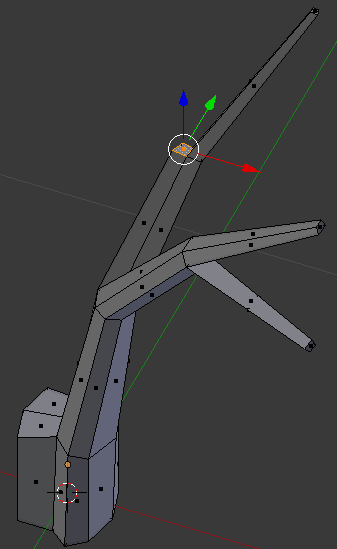
- Press E to extrude
- Type .85 and press Enter
- Press G to move the faces
- Press X to move horizontally
- Type -.1 and press Enter
- Press S to resize it
- Type .5 and press Enter:
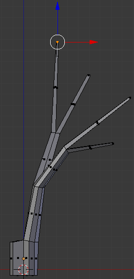
- Press G to move the faces
- Press Y to move horizontally
- Type .5 and press Enter
- On the menu bar of the 3D-View, click the Vertex Select button

- Right-click the vertex inside the branches:
- Press G to move the vertex
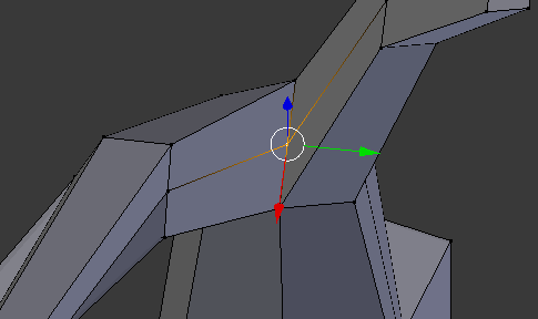
- Press Z to move horizontally
- Type .075 and press Enter
- Right-click the inside vertex below the top two branches:
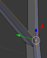
- Press G to move the vertex
- Press Y to move horizontally
- Type -1.01 and press Enter
- In the same way, move each intersecting vertex slightly away from its faces
 Practical Learning: Creating the Second Part of a Tree
- Select the original faces that were left
- Right-click the other top-right face:

- Press E to extrude
- Type .35 and press Enter
- On the menu bar of the 3D-View, click the Vertex Select button

- Right-click the middle-back vertex:
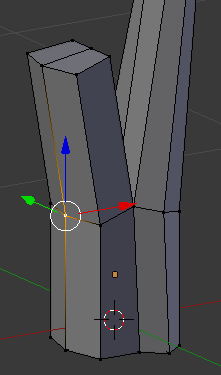
- Press G to move it
- Press X to move in that axis
- Type -.01 and press Enter
- Right-click the vertex inside the main branches:
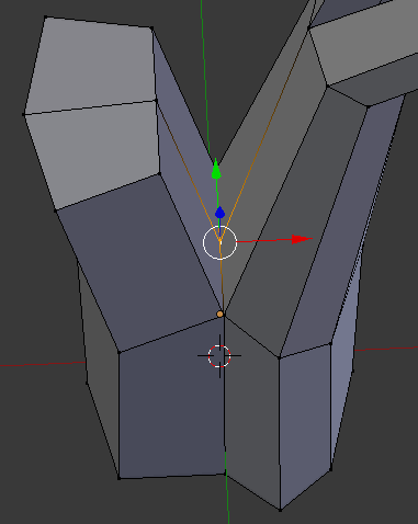
- Press G to move the vertex
- Press Z to move horizontally
- Type .1 and press Enter
- Right-click the interior vertex between the top two faces:
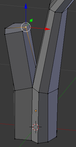
- Press G to move the vertex
- Press X to move vertically
- Type .015 and press Enter
- Right-click one of the vertices on the other side
- Press and hold Shilft
- Right-click the vertex on the other side
- Release Shift:
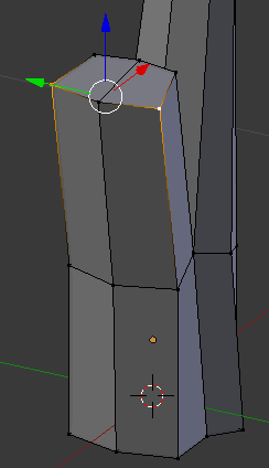
- Press S to resize
- Type .75 and press Enter
- On the menu bar of the 3D-View, click the Face Select button

- Right-click one of the top faces
- Press and hold Shift
- Right-click the other top face:
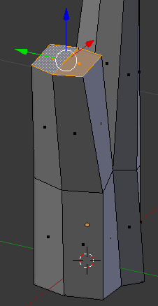
- Press E to extrude the faces
- Type .5 and press Enter
- Press S to resize
- Type .8 and press Enter
- Press G to move the faces
- Press X to move them horizontally
- Type -.05 and press Enter:
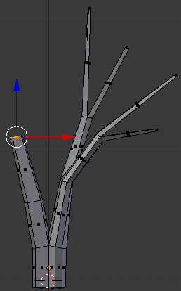
- While the faces are still selected, press G to move
- Press Y
- Type -.075 and press Enter
- On the menu bar of the 3D-View, click the Edge Select button

- Move the object to see the top faces and right-click the top-central edge to select it:
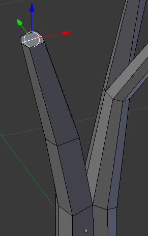
- Press G to move the edge
- Press Z to move it vertically
- Type .02 and press Enter
- On the menu bar of the 3D-View, click the Face Select button

- Right-click the top face behind the origin on the Y axis:
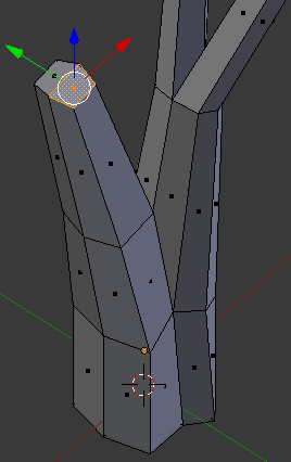
- Press E to extrude
- Type .5 and press Enter
- On the menu bar of the 3D-View, click the Edge Select button

- Right-click the inside edge:
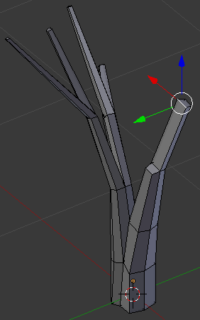
- Press S to resise the edge
- Type .75 and press Enter
- Press Ctrl + R and get a vertical cut
- Click twice to confirm:
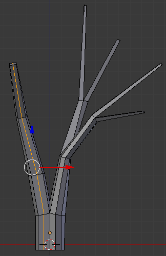
- On the menu bar of the 3D-View, click the Face Select button

- Right-click the top-interior face:
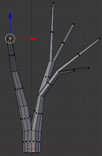
- Press E to extrude
- Type .2 and press Enter
- Press S to resize the face
- Type .75 and press Enter
- Press G to move the face
- Press X to move horizontally
- Type .05 and press Enter:
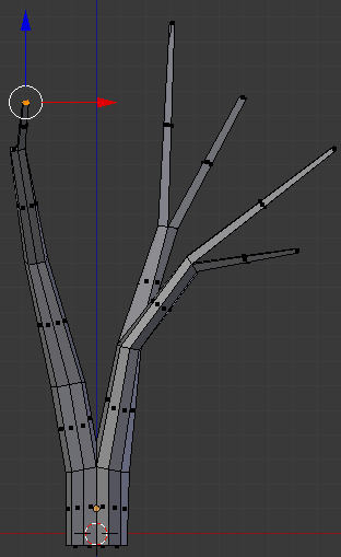
- Move the object and right-click the face that was previously left
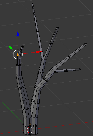
- Press E to extrude
- Type .75 and press Enter
- Press S to resize it
- Type .65 and press Enter
- Press G to move the faces
- Press X to move horizontally
- Type -.15 and press Enter:
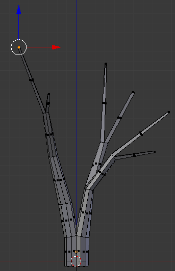
- Press G to move the faces
- Press Y to move horizontally
- Type -.25 and press Enter
- Move the object around and right-click the interior face that were left:
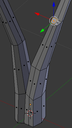
- Press E to extrude
- Type .25 and press Enter
- Press G to move the faces
- Press X to move horizontally
- Type .2 and press Enter
- Press S to resize it
- Type .5 and press Enter:
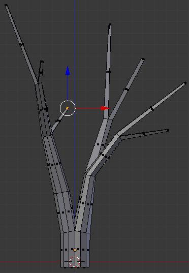
- Move the object around and right-click the face that was left:
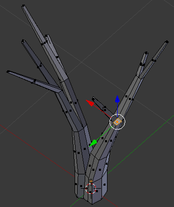
- Press E to extrude
- Type .55 and press Enter
- Press G to move the faces
- Press X to move horizontally
- Type -.35 and press Enter
- Press S to resize it
- Type .5 and press Enter:
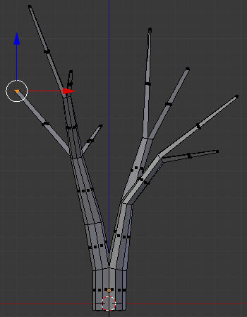
- Press E to extrude
- Type .25 and press Enter
- Press S to resize it
- Type .5 and press Enter
- Press G to move the face
- Press X to move along that axis
- Typpe -.5 and press Enter:
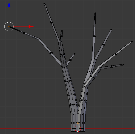
- On the menu bar of the 3D-View, click the Vertex Select button

- Right-click the bottom-outside vertex of the newly create cut:
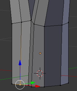
- Press G to move the face
- Press Y to move horizontally
- Type -.02 and press Enter
- Right-click the vertex above the one you had previously used:
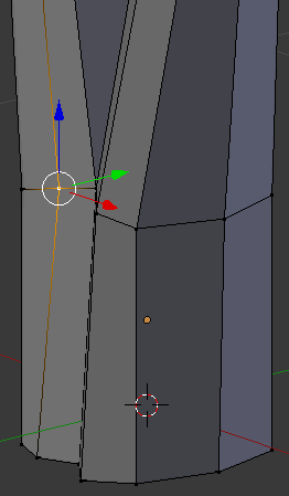
- Press G to move the edge
- Press Y to move them along that axis
- Type -.02 and press Enter
- In the same way, move away the middle of three vertices that have the same alignment
- On the menu bar of the 3D-View, click Edit Mode and click Object Mode:
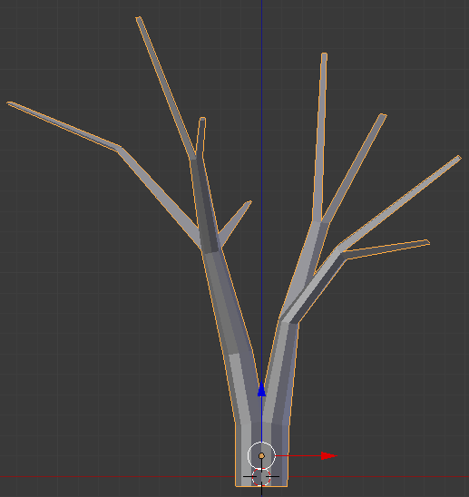
- In the Create tab of the Tools window, click Ico Sphere
- In the Object tab of hte Properties window, change the following values:
Location - X: 5.15
		     Y: 2.235
           Z: 1.95
Scale    - X: 1
		     Y: 1
           Z: .75
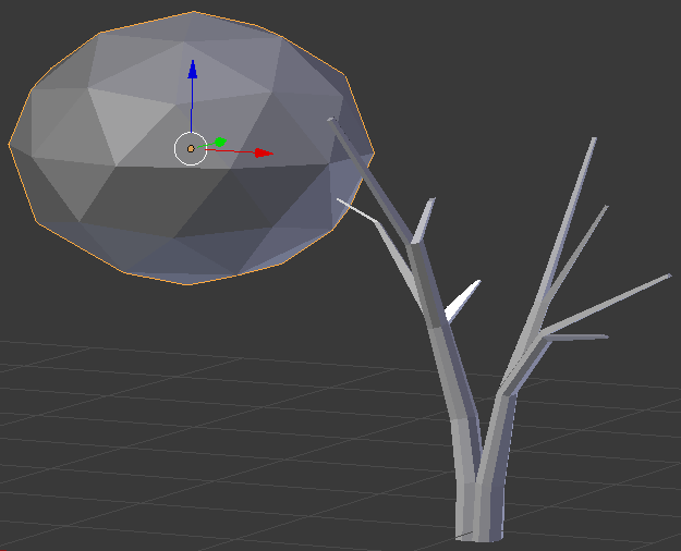
- In the Create tab of the Tools window, click Ico Sphere
- In the Object tab of hte Properties window, change the following values:
Name:      Quarters
Location - X: 6.35
		     Y: .9
           Z: 2.7
Scale    - X: .75
		     Y: .75
           Z: .55
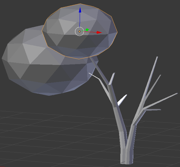
- In the Create tab of the Tools window, click Ico Sphere
- In the Object tab of hte Properties window, change the following values:
Location - X: 6.625
		     Y: 2.06
           Z: 2.05
Scale    - X: .5
		     Y: .5
           Z: .35

- In the Create tab of the Tools window, click Ico Sphere
- In the Object tab of hte Properties window, changethe following values:
Location - X: 7
		     Y: 2.04
           Z: 1.55
Scale    - X: .3
		     Y: .3
           Z: .3
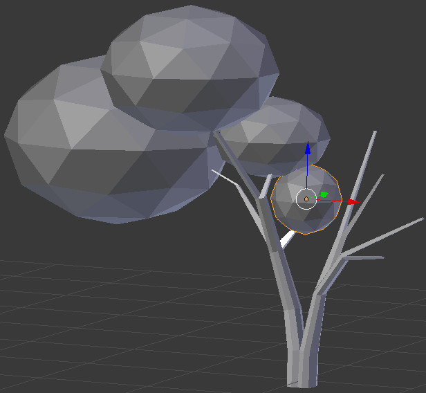
- In the Create tab of the Tools window, click Ico Sphere
- In the Object tab of hte Properties window, changethe following values:
Location - X: 7.25
		     Y: 3
           Z: 3
Scale    - X: 1.25
		     Y: 1.25
           Z: 1
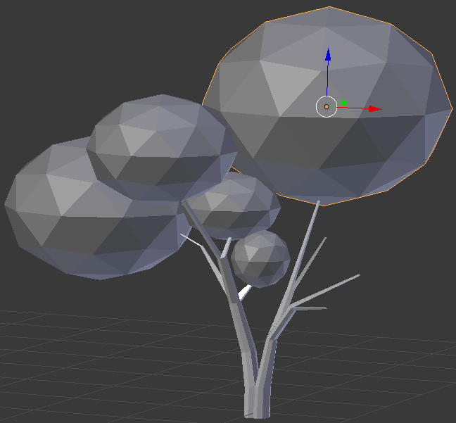
- In the Create tab of the Tools window, click Ico Sphere
- In the Object tab of hte Properties window, changethe following values:
Location - X: 7.8
		     Y: 2.2
           Z: 2
Rotation - X: -10
		     Y: 35
Scale    - X: .25
		     Y: .25
           Z: .5
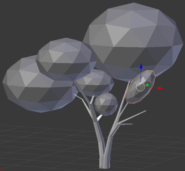
- In the Create tab of the Tools window, click Ico Sphere
- In the Object tab of hte Properties window, changethe following values:
Location - X: 8.4
		     Y: 2
           Z: 1.65
Rotation - Y: -30
Scale    - X: .5
		     Y: .5
           Z: .35
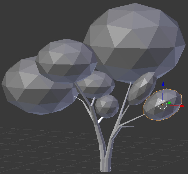
- In the Object tab of hte Properties window, changethe following values:
Location - X: 8.2
		     Y: 1.8
           Z: 1.05
Scale    - X: .5
		     Y: .5
           Z: .35
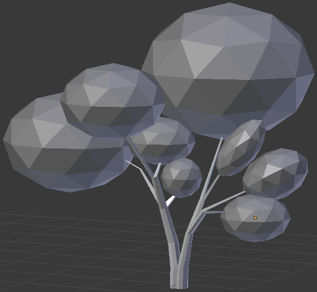
The above numbers are simple indications.Otherwise, adjust the branches isze, and the leaves locations and sizes until you are satisfied. Here is an example:
 Practical Learning: Modeling a Stone
- In the Create tab of the Tools window, click Ico Sphere
- In the Object tab of the Properties window, change the following values:
Name:      Stony Foyer
Location - X: -5
		     Y: 0
           Z: .35
Rotation - Z: -40
Scale    - X: 2
		     Y: 3
           Z: 1.5
- On the menu bar of the 3D View, click Object Mode and click Edit Mode
- On the Menu that appears, click Enable

- On the menu bar of the 3D View, click the Proportional Editing Fallof button and click Sphere
- Move the shape around and right-click a vertex (any) on the bottom side of the sphere
- Press G
- Roll the mouse wheel a few time to get a circle that includes the vertex and other vertices around it. Here is an example (you don't have to right-click the same vertex):
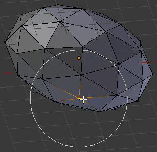
- Move the mouse slightly up as if you are flattening the base
- On the menu bar of the 3D-View, click the Face Select button

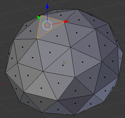
- Move the sphere around and right-click a face in the top side (no need for precision):
- Press and hold Shif
- Right-click the other faces that make up a star
- Release Shift. Here is an example:
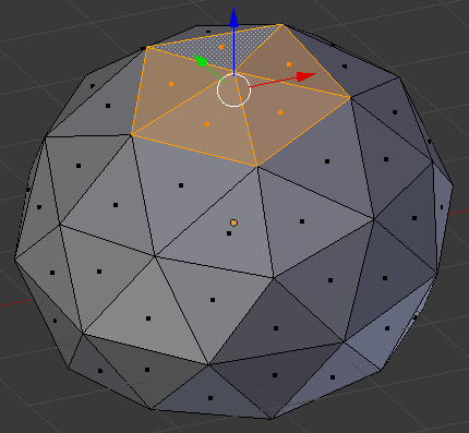
- Position the mouse on the selection and press G
- Move the mouse towards the sphere and click. Here is an example:
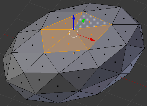
- On the menu bar of the 3D View, click the Proportional Editing button and click Disable
- On the menu bar of the 3D View, click Edit Mode and click Object Mode
 Practical Learning: Creating a Rock
- In the Create tab of the Tools window, click Ico Sphere
- In the Object tab of the Properties window, change the following values:
Name:      Season Wrap
Location - X: 20
		     Y: -20
           Z: .05
Rotation - X: -20
		     Y: 20
Scale    - X: 2
		     Y: 3
           Z: 1.5
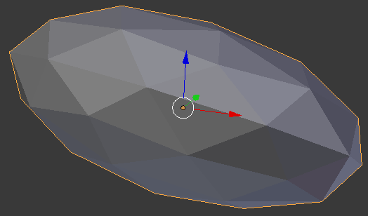
 Practical Learning: Creating a Stone
- On the menu bar of the 3D View, click Add -> Mesh -> Ico Sphere
- On the Add Ico Sphere section below the Tools window, set the Subdivisions value to 3
- On the Object tab of the Properties window, change the following values:
Name:      Rolling Side
Location - X: 10.5
		     Y: -30
           Z: .5
Rotation - Z: 60
Scale:   - X: 2
		     Y: 1
           Z: 1
- Press Tab to enter into Edit Mode
- Position the mouse on the ico-sphere and press A to deselect everything
- On the menu bar of the 3D-View, click the Vertex Select button

- On the menu bar of the 3D View, click Select and click Random. Here is an example (of course, your selection will be different from the following):
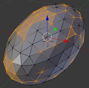
- Press G to prepare to move the selected vertices
- Move the mouse slightly along the red arrow (the X axis). Here is an example (of course, your selection will be different from the following):
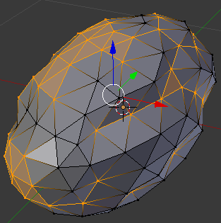
- Press A to deselect everything
- On the menu bar of the 3D View, click Select and click Random. Here is an example (of course, your selection will be different from the following):
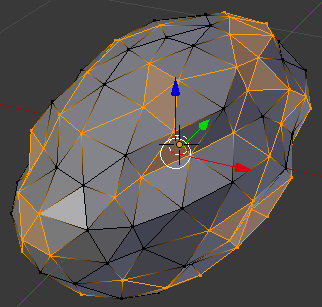
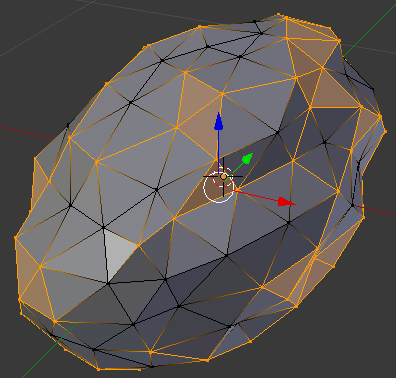
- Press S to move the selected vertices
- Move the mouse slightly away from the object. Here is an example (of course, your object will appear different from the following):
- On the menu bar of the 3D View, click Edit Mode and click Object Mode
 Practical Learning: Setting a Desert Landscape
- In the Outliner, click the Restricted Viewport Visibility button (the eye) on the right side of Ascension to display it
- In the Outliner, click the Restricted Viewport Visibility button on the right side of Half Tail to display it
- In the Outliner, click the Restricted Viewport Visibility button on the right side of Pitcher to display it
- In the Outliner, click the Restricted Viewport Visibility button on the right side of Facial Works to display it
- In the Outliner, click the Restricted Viewport Visibility button on the right side of April Fish to display it
- In the Outliner, click the Restricted Viewport Visibility button on the right side of Cake Off to display it
- In the Outliner, click the Restricted Viewport Visibility button on the right side of Provincial to display it
- In the Outliner, click the Restricted Viewport Visibility button on the right side of Oversight to display it
- In the Outliner, click the Restricted Viewport Visibility button on the right side of Oak Mali to display it
- In the Create tab of the Tools window, click Plane
- In the Object tab of the Tools window, change the following values:
Name:      Desert Floor
Location - X: -5
			 Y: 5
           Z: .02
Scale    - X: 32
		  	 Y: 45
- In the Numeric Pad, press 0 to display the camera view
- Press N to display the Properties Region
- In the Properties Region, click Lock Camera to View to check it
- In the Outliner, click Camera to select it
- In the Object tab of the Properties window, change the following values:
Location - X: 28
			 Y: -50
			 Z: 8.15
Rotation - X: 78
			 Y: 0
           Z: 30
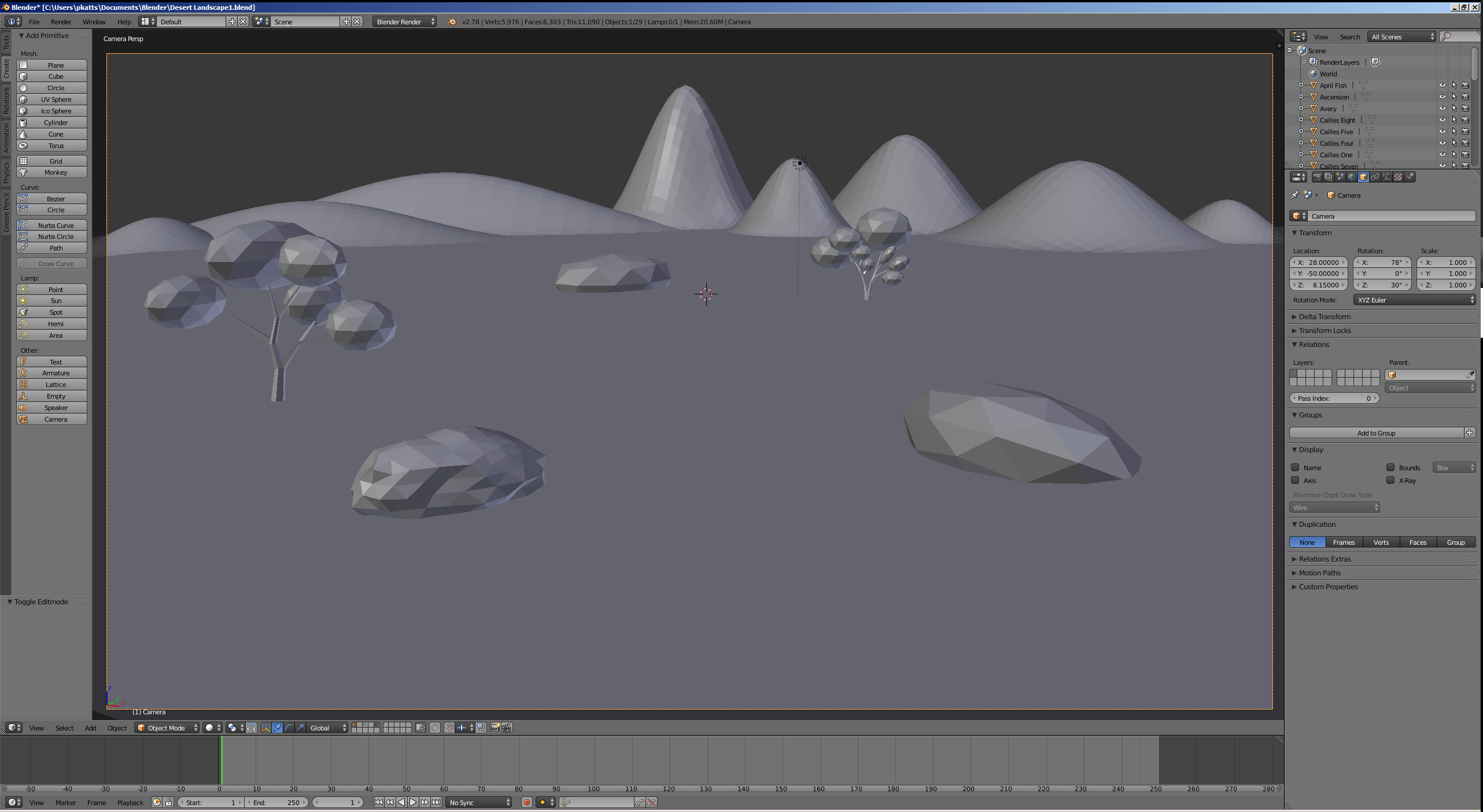
- Press N to close the Properties Region
 Practical Learning: Applying Primary Materials
- On the top menu bar, click Blender Render and select Cycles Render
- In the Properties window, in the Render section, click 50%, type 100 and press Enter
- Click the Sampling button to expand it
- Change the Render value to 500
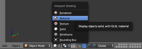
- On the menu bar of the 3D View, click the Viewport Shading button and select Material:
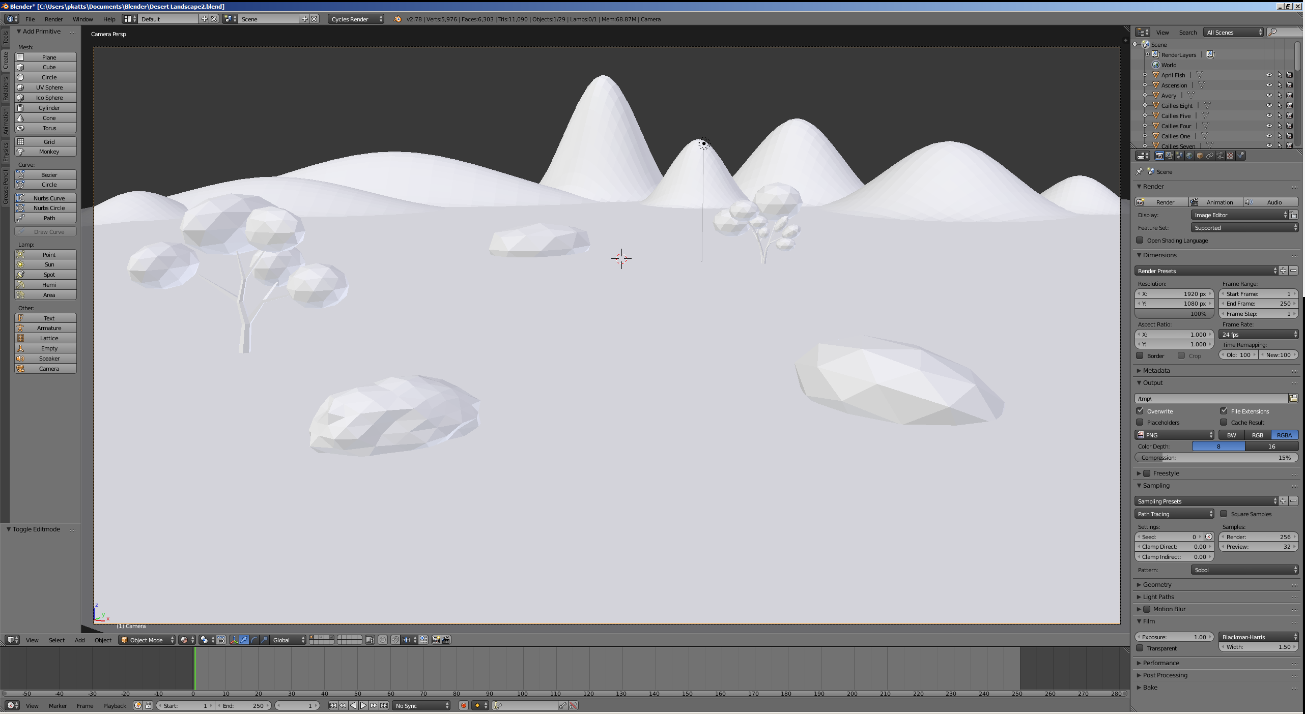
Introduction to Inputs
An input is a piece of information that complements a material. Cycles Render supports two categories of inputs: simple and composite. A simple input is one that includes one value and can be added with a one window.
 Practical Learning: Creating a Node Editor
- In the top-right side of the 3D View, position the mouse inside the small triangle until a + button appears:
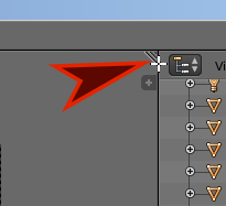
- Click and drag down to create a window
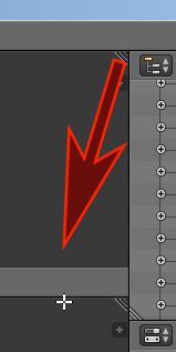
- Ten release the mouse
- Click the button in the bottom-left side of the new window and click Node Editor:

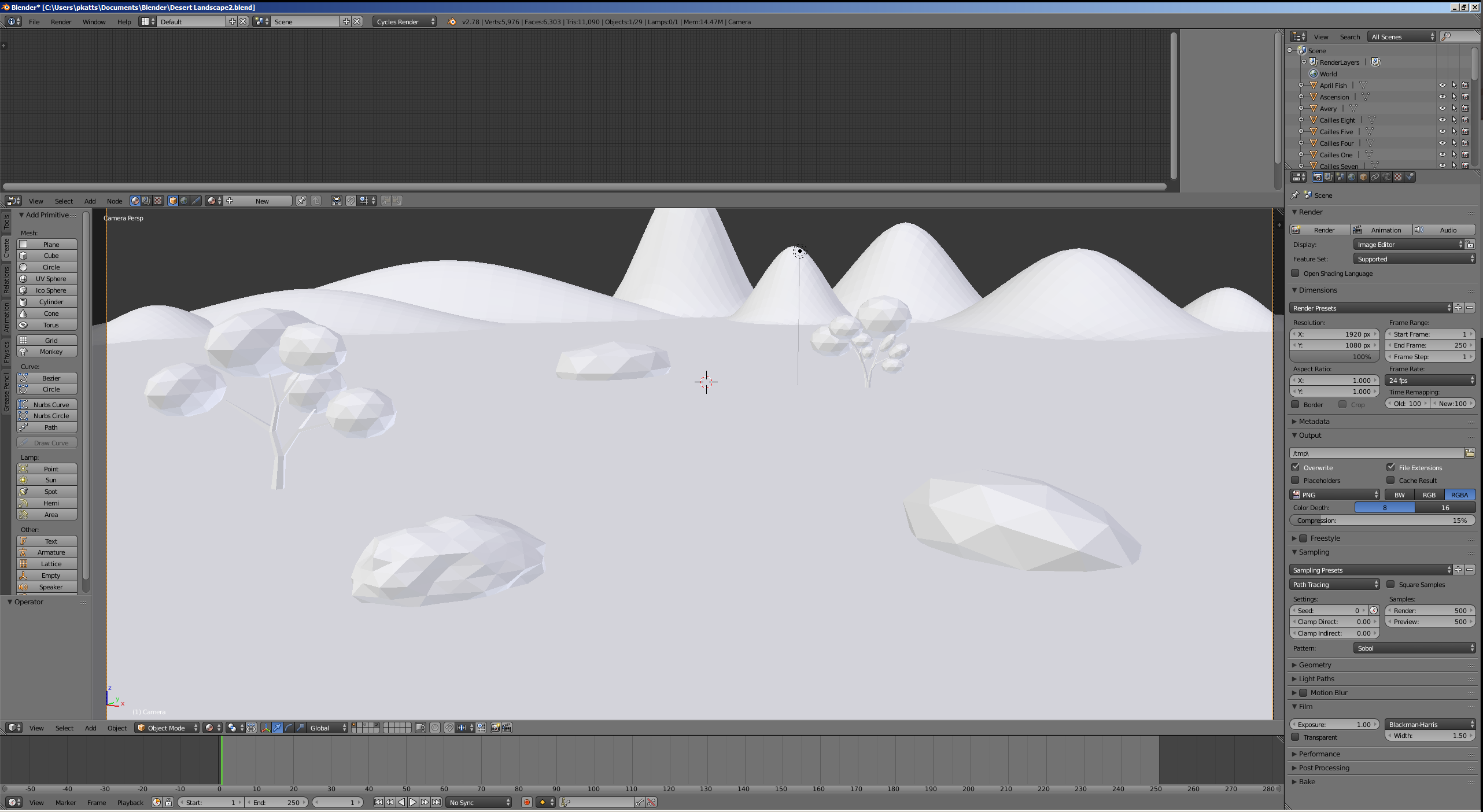
Simple Inputs: The RGB Input
As you may remember, many materials (such as Diffuse, Glass, Glossy, Emission, and Background, just to name a few) have a Color characteristic that is used to paint an object. Many of those materials also have a roughness characteristic that is a floating-point number. To specify the color of a material, you can click the Color button. This would open a small window that contains a color wheel, a vertical color bar, a horizontal color bar, and text boxes. After selecting or specifying a color, the small window would close. As an alternative, Cycles Render provides an input named RGB.
If you select the RGB input in the Properties window, a small window would display. If you add it using the Node Editor, connect its Color button to the Color button of the material. After selecting or adding the RGB input, it would be available in the Properties window, in the Node Editor, and in the Properties Region of the Node Editor. The difference and advantage are that, while the local Color window closes after use, the RGB color window remains open.
 Practical Learning: Adding an RGB Input
- In the Properties window, click the Material button

- In the Properties window, click the World button

- In the Properties window, click the Use Nodes button
- Click the dark-gray button
 on the right side of the black button of the Color button
- In the window that appears, click RGB
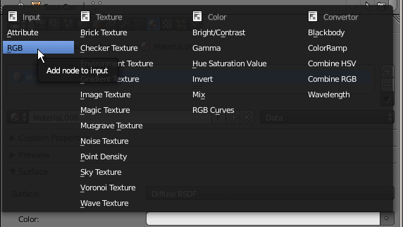
- In the color wheel, select a light blue color
- Click the horizontal bar below the color wheel and set the color as follows:
R: .65
G: .75
B: .855
- In the Render section, click the Render button:
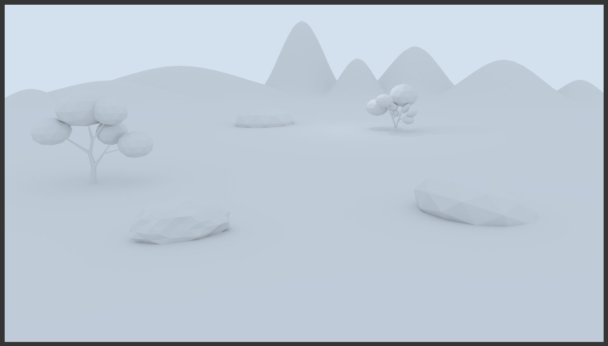
- After viewing the results, press Esc
- In the Outliner, click Desert Floor to select it
- In the Properties window, click the New button
- Zoom in the Node Editor as much as possible to be able to read the contents of the windows
- In the Properties window, click the dark-gray button
 on the right-side of the white horizontal bar on the right side of Color
- In the window that appears, click RGB
-

- Still in the Properties window, click inside the color wheel to select a color close to mud
- Click the horizontal bar below the color wheel and click RGB, then set a color as follows:
R: 0.800
R: .45
B: .2
- In the Outliner, click Oversight to select it
- On the menu bar of the Node Editor, click the New button
- Still on the menu bar of the Node Editor, click Material.002 to select the name
- Type Brown Starch and press Enter
- On the menu bar of the Node Editor, click Add -> Input -> RGB
- Position the new window on the left side of hte Diffuse BSDF and click
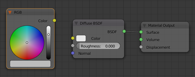
- Drag the yellow button from the RGB window and drop it on the yellow button of Diffuse BSDF
- Click the horizontal bar below the color wheel and set the color as follows:
R: .115
G: .025
B: .005

- In the Outliner, click Provincial to select it
- In the Material section of the Properties window, click the New button
- On the menu bar of the Node Editor, click Material.003 to select the name
- Type Light Cocoa and press Enter
- In the Material section of the Properties window, click the dark-gray button on the right-side of the white bar of Color and click RGB
- In the Node Editor, in the RGB window, click the horizontal bar below the color wheel and set the RGB values as follows:
R: .25
G: .15
B: .065
- In the Outliner, click Cake Off to select it
- On the menu bar of the Node Editor, click the New button
- Still on the menu bar of the Node Editor, click Material.003 to select the name
- Type Salmonica and press Enter
- In the Properties window, click the dark-gray button on the extreme right-side of Color and click RGB
- In the Node Editor, click the horizontal bar below the color wheel and set the color as follows:
R: .105
G: .025
B: .005
- In the Outliner, click Pitcher to select it
- On the menu bar of the Node Editor, click the New button
- In the Material section of the Properties window, click Material.003 to select the name
- Type Burried Cane and press Enter
- In the Material section of the Properties window, click the dark-gray button on the right-side of the white bar of Color and click RGB
- In the Node Editor, in the RGB window, click the horizontal bar below the color wheel and set the RGB values as follows:
R: .315
G: .185
B: .075
- In the Outliner, click Stony Foyer to select it
- In the Properties window, click the New button
- Still in the Properties window, click Material.003 to select the name
- Type Gray and press Enter
- Still in the Properties windows, click the dark-gray button on the extreme right-side of Color and click RGB
- In the Node Editor, click inside the vertical bar on the right-side of the color wheel and select a gray color (alternatively, click the horizontal bar below the color wheel and set the color as follows: R = .255, G = .255, B = .205)
- In the Outliner, click April Fish to select it
- In the Material section of the Properties window, click the button on the left side of New and select Burried Cane
- In the Outliner, click Facial Works to select it
- On the menu bar of the Node Editor, click the button on the left side of New and select Salmonica
- In the Outliner, click Half Tail to select it
- In the Properties window, click the button on the left side of New and select Brown Starch
- In the Outliner, click Ascension to select it
- On the menu bar of the Node Editor, click the button on the left side of New and select Light Cocoa
- In the Outliner, click Season Wrap to select it
- On the menu bar of the Node Editor, click the button on the left side of New and select Gray
- In the Outliner, click Rolling Side to selet it
- On the menu bar of the Node Editor, click the button on the left side of New and select Gray
- In the Outliner, click Classic Tree to select it
- In the Material section of the Properties, click the button on the left side of New and select Brown Starch
- In the Outliner, click Double-Tree to select it
- On the menu bar of the Node Editor, click the button on the left side of New and select Brown Starch
- In the Outliner, click Summer Stretch to select it
- On the menu bar of the Node Editor, click the New button
- In the Material section of the Properties window, click Material.002 to select it
- Type Regular Green and press Enter
- In the menu window that appears, click RGB
- In the Node Editor, click inside the color wheel and select a normal green color
- Still in the Node Editor, click the horizontal bar below the color wheel and set the RGB value as follows:
R: 0
G: .5
B: 0
The Value Input
Many materials use numeric values. Probably the most common numeric value is the roughness. To set such a characteristics, you can use its button on the material window in the Properties window or the Node Editor. To provide an alternative, Cycles Render provides an input named Value.
 Practical Learning: Introducing Cycles Render
- In the Properties window, click the dark gray button on the right side of 0.000 on the right-side of Roughness
- In the menu that appears, click Value
- In the Node Editor, click the Roughness value, type .25
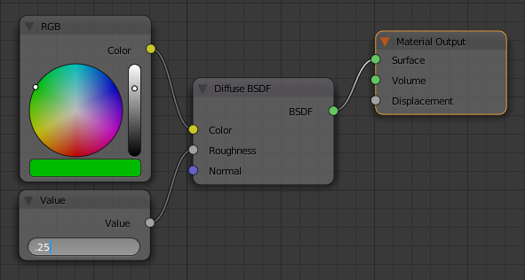
- Press Enter
- In the Outliner, click Eau Claire to select it
- On the menu bar of the Node Editor, click the New button
- On the menu bar of the Node Editor, click Material.003 to select the name
- Type Dark Green and press Enter
- In the Properties window, click the dark-gray button on the right-side of Color and click RGB
- In the Material section of the Properties window, click the horizontal bar below the color wheel and set the color as follows:
R: 0
G: .135
B: .005
- On the menu bar of the Node Editor, click Add -> Input -> Value
- Position the window below the RGB window
- In the Value window, click the 0.500 value to select it
- Type .75 and press Enter
- Drag the gray button from the Value window and drop it on the Roughness gray button of the Diffuse BSDF window
- In the Outliner, click High Hope to select it
- On the menu bar of the Node Editor, click the New button
- In the Properties window, double-click Material.003 to select the name
- Type Light Green and press Enter
- In the Material section of the Properties window, click the dark-gray button of Color and click RGB
- Click the horizontal bar below the color wheel and click Hex
- Set the color value as 2AFF2C and press Enter
- In the Properties window, click the dark-gray button on the right side of Roughness and click Value
- In the Node Editor, click the value of Roughness to select it
- Type .885 and press Enter
- In the Outliner, click Quarters to select it
- On the menu bar of the Node Editor, click the New button
- Still on the menu bar of the Node Editor, click Material.004 to select the name
- Type Yellow Leaven and press Enter
- In the Material section of the Properties window, click the dark-gray button on the right side of Color and select RGB
- Click the horizontal bar below the color wheel, click Hex, set its value as adff2f and press Enter
- For each of the other leaves, right-click a leaf to select it, in either the Node Editor or the Material section of the Properties window, click the button on the left side of New and select one of Dark Green, Regular Green, Light Green, or Yellow Leaven
- In the top-right side of the 3D View, click inside the small triangle drag it up completely to close the Node Editor:
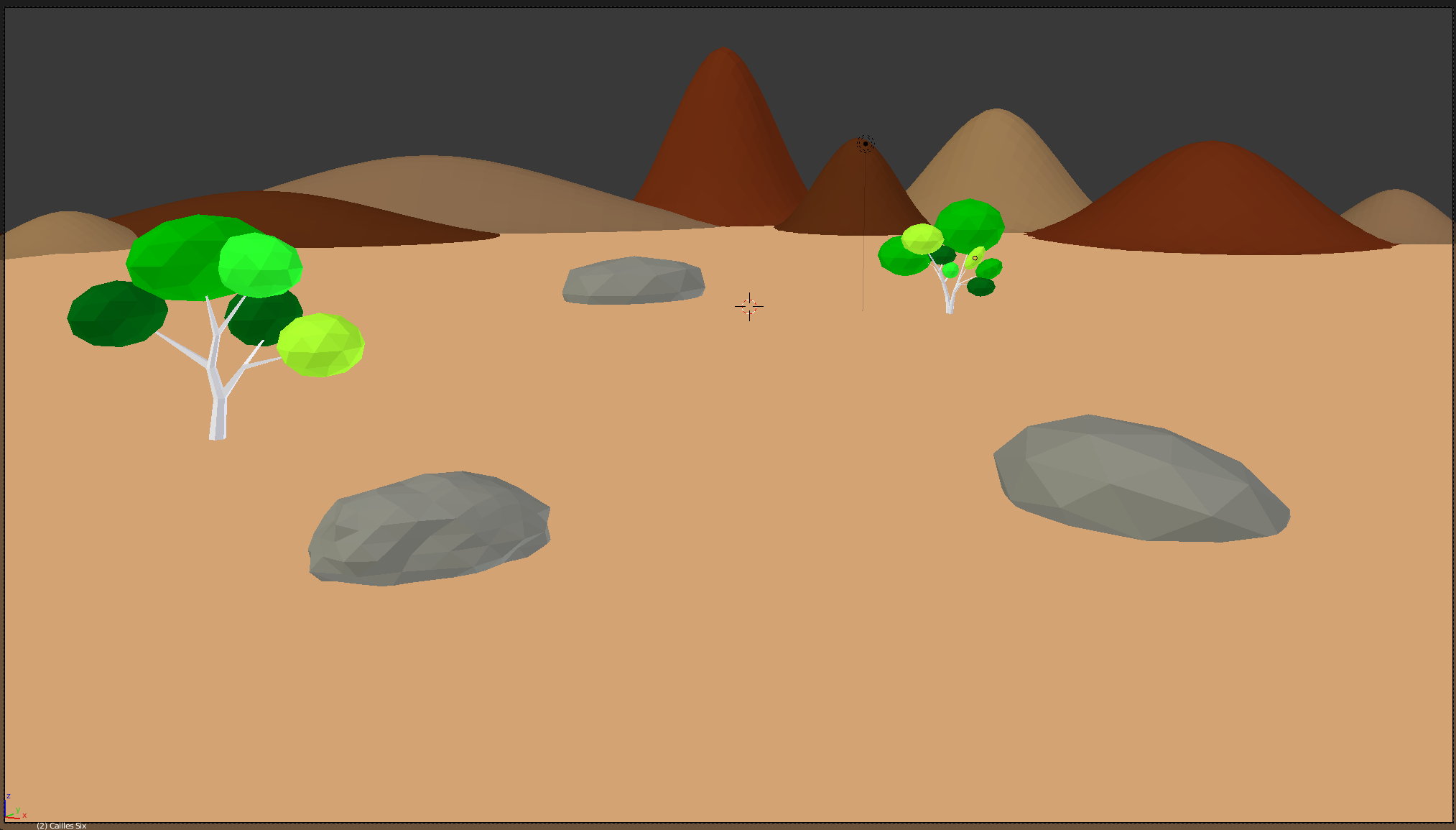
- In the Properties window, click the Render button

- In the Render section, click the Render button:

- After viewing the results, press Esc


![]() Practical Learning: Starting the Project
Practical Learning: Starting the Project![]() Practical Learning: Creating a Regular Hill
Practical Learning: Creating a Regular Hill


![]() Practical Learning: Modeling a Tree
Practical Learning: Modeling a Tree


![]() Practical Learning: Creating the First Part of a Tree
Practical Learning: Creating the First Part of a Tree


![]() Practical Learning: Creating the Second Part of a Tree
Practical Learning: Creating the Second Part of a Tree


![]() Practical Learning: Modeling a Stone
Practical Learning: Modeling a Stone


![]() Practical Learning: Creating a Rock
Practical Learning: Creating a Rock
![]() Practical Learning: Creating a Stone
Practical Learning: Creating a Stone


![]() Practical Learning: Setting a Desert Landscape
Practical Learning: Setting a Desert Landscape![]() Practical Learning: Applying Primary Materials
Practical Learning: Applying Primary Materials
![]() Practical Learning: Creating a Node Editor
Practical Learning: Creating a Node Editor


![]() Practical Learning: Adding an RGB Input
Practical Learning: Adding an RGB Input


![]() Practical Learning: Introducing Cycles Render
Practical Learning: Introducing Cycles Render