 |
Blender Materials: Introduction to Textures |
|
Introduction
A texture is a design that influences how a color is applied to an object. Cycles Render supports two type of textures: design-based textures and images.
In this lesson, we will model a kapsiki house. The house is made of two parts: The bottom part is one cylindrical wall with one door and one window. The roof is a cone covered with straw.
 Practical Learning: Setting Up the Scene
- Start Blender
- In the Properties window, click the Object button

- In the work area, right-click the default cube to make sure it is selected. Press X
- In the menu that appears, click Delete to remove it
Practical Learning: Modeling the House
- To add a shape, in the Tools window, click the Create tab
- In the Mesh section, click Circle
- In the Add Circle section below the Tools window, change the Radius value to 2
- Position the mouse in the work area and press Tab to switch to Edit Mode
- Press E to extrude
- Press Z to extrude vertically
- Type 3.25 and press Enter:

- Press Ctrl + R to create a cut
- Move the mouse on the shape until a horizontal cut appears, then click
- Type -.75 and press Enter:
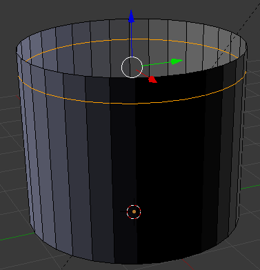
- On the menu bar below the work area, click the Edge Select button

- On the cylinder, right-click any vertical line below the cut
- Press and hold Shift
- Right-click 2 other vertical lines close to the previously selected one to get 3 consecutively selected edges:
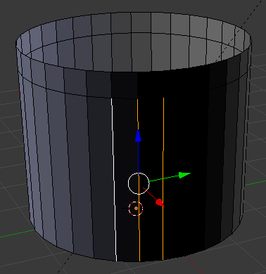
- Right-click each of the edges below those lines and right-click the edges on both sides
- Release Shift:
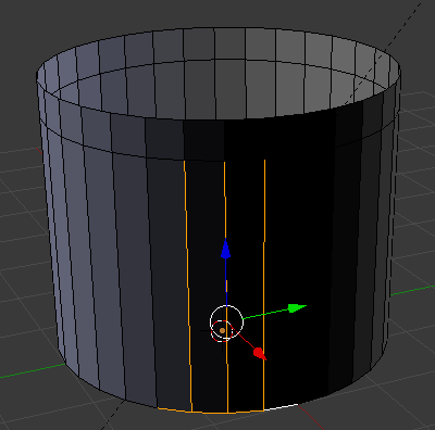
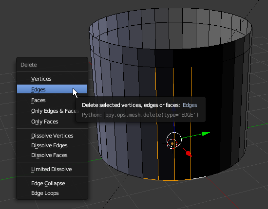
- Press X
- In the menu that appears, click Edges:
:
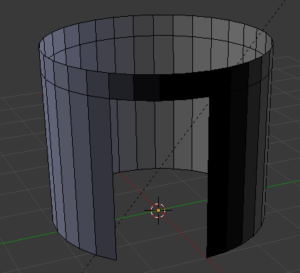
- Press Ctrl + R to create a cut
- Move the mouse on the shape until a horizontal cut appears, then roll the middle mouse button to get 2 horizontal lines
- Click twice to accept the cuts
- Press and hold Alt
- Right-click the top one of the cuts that were just made
- Release Alt:
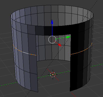
- Press G to move the cut
- Press Z to restrict the move vertically
- Type .5 and press Enter:
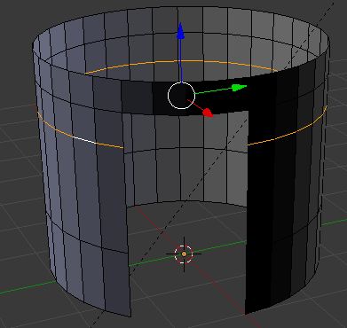
- Press and hold Alt
- Right-click the other cut that was just made
- Release Alt
- Press G to move the cut
- Press Z to restrict the move vertically
- Type .85 and press Enter:
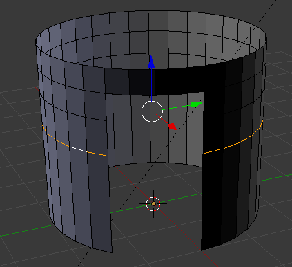
- Move the view a little bit horizontally so you can see one of the sides of the door or the back of the house (it's up to you):
- Right-click a vertical edge between the horizontal lines:
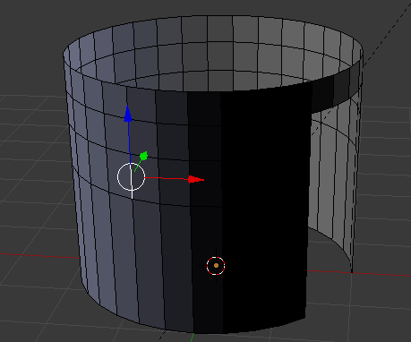
- Press and hold Shift
- Right-click 1 other vertical line close to the previously selected one but not next to the door to get 2 consecutively selected edges
- Release Shift:
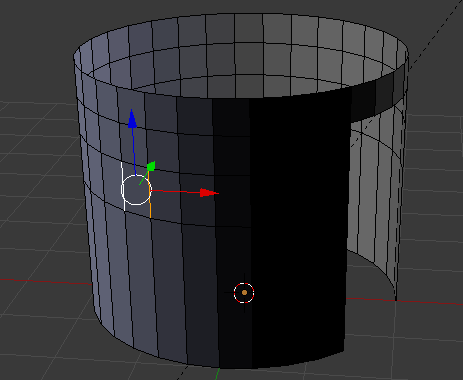
- Press X
- In the menu that appears, click Edges:
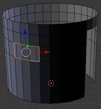
- Press Tab to display in the Object Mode
- In the Properties window, click the Object Modifier button
- Click Add Modifier and click Solidify
- Change the Thickness to .2
- Click Apply:
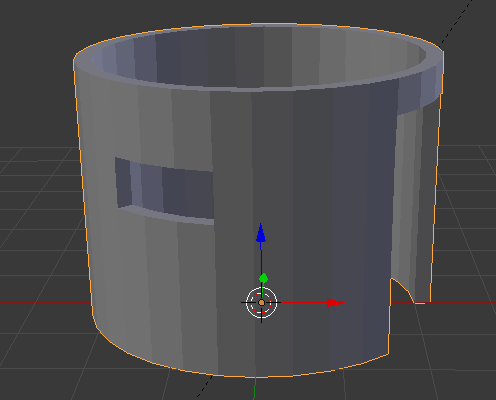
- Click Add Modify again and click Subdivision Surface
In the Subdivisions section, set the View value to 2
- Move the house so the door is in front of you and zoom it to see it as much as possible
- Press Tab to switch to Edit Mode
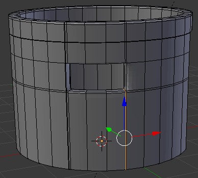
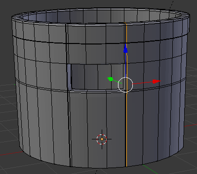
- Position the mouse on the house. Press Ctrl + R to create a cut
- Move the mouse up above the door then click
- Move the mouse up to place the cut as close as possible to the top border (it doesn't matter if you touch the border or not):
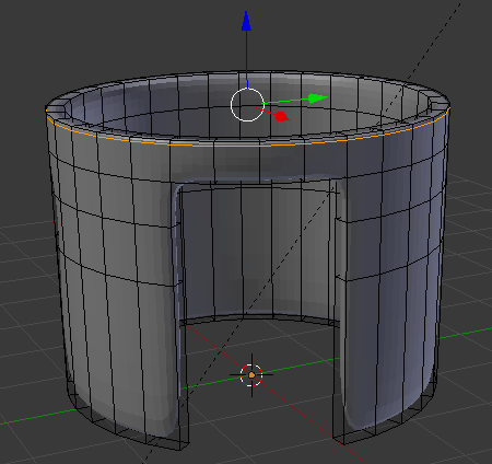
- In the same way, create and position the cuts as follows:
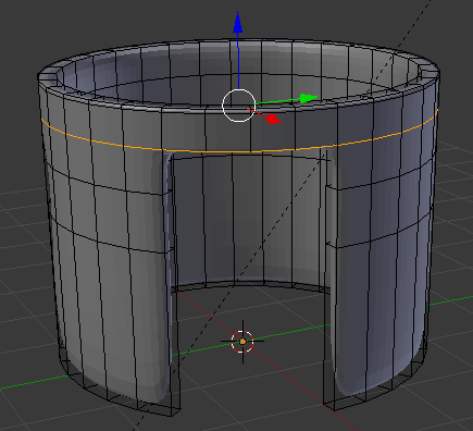
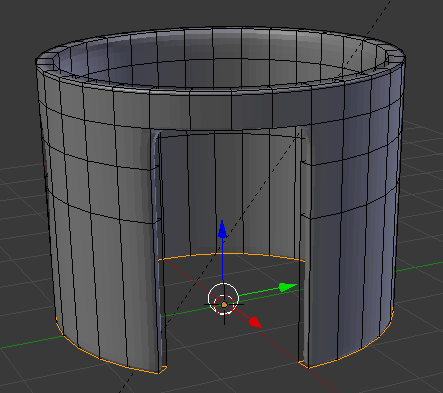
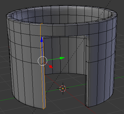
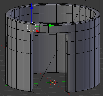
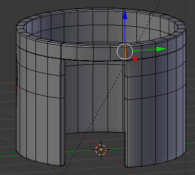
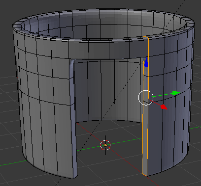
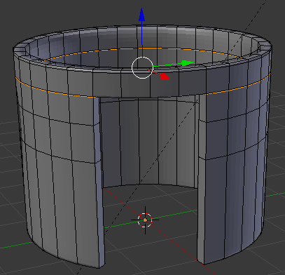
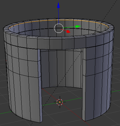
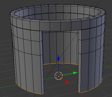
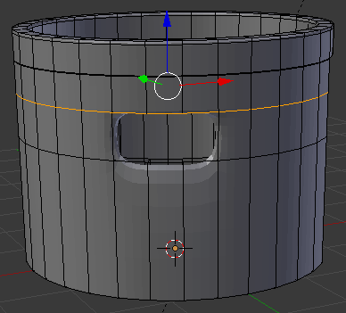
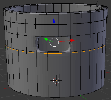
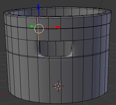
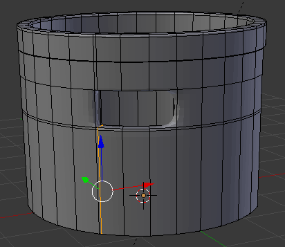
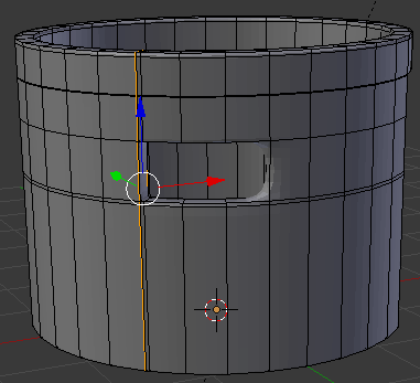
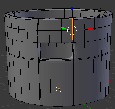
- Press Tab to display the shape in Object Mode
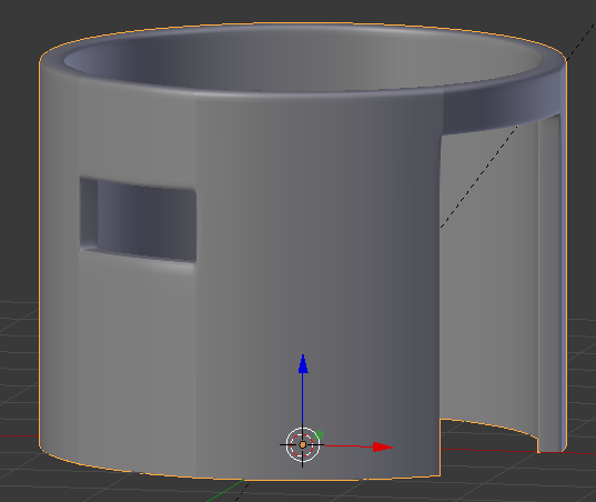
- In the Properties window, click Apply
- In the Tools window, click the Tools tab and click Smooth
- In the Properties window, click the Object button
- In the Properties window, click Circle to select it, type Common Wall and press Enter
 Practical Learning: Modeling the Roof
- Move the view so you can see the top of the cone
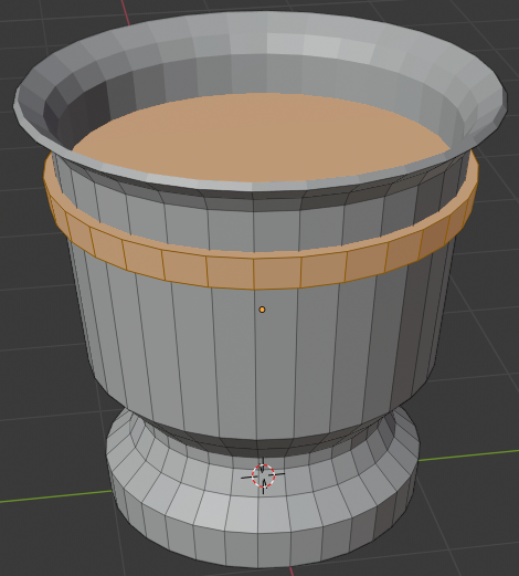
On the menu bar of the 3D View, click Add -> Mesh -> Cone
- In the Add Cone section below the Tools window, change the following values:
Radius 1:  2.75
Radius 2:  1.55
Depth:     1.125
Location - Z: 3.75
- Press Tab to display the cone in Edit Mode
- On the menu bar of the 3D-View, click the Face Select button

- Right-click the top of the cone to select the top face:
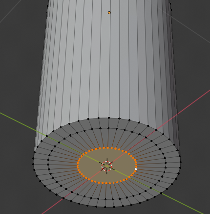
- Press E to extrude
- Type .95 and press Enter:
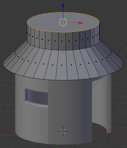
- Press S to resize
- Type .525 and press Enter:
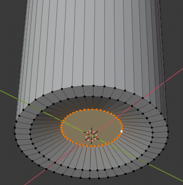
- Press E to extrude
- Type .75 and press Enter:
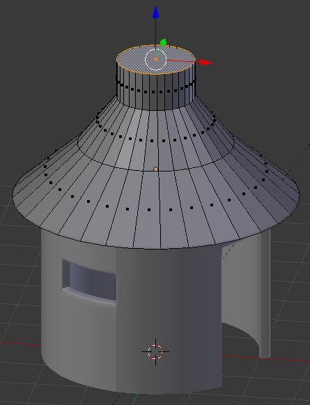
- Press S to resize
- Type .55 and press Enter:
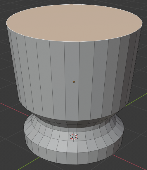
- Press E to extrude
- Type 1.5 and press Enter
- Press S
- Type 0 and press Enter:
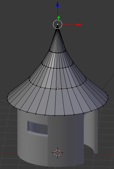
- Press Tab to display the cone in Object Mode
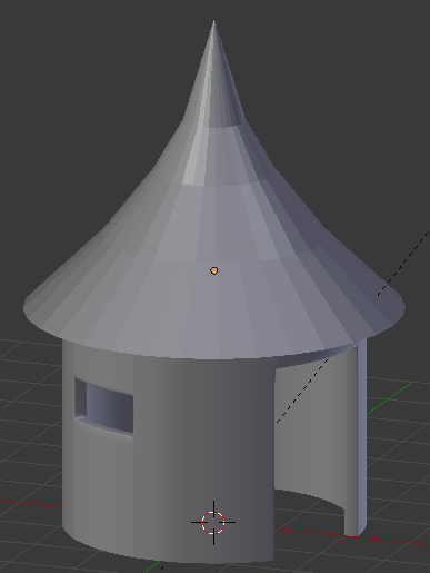
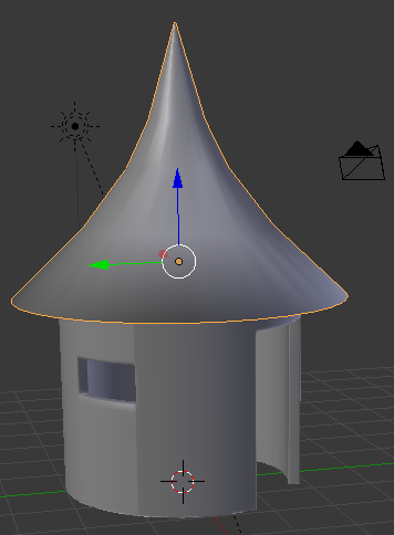
- In the Tools window, click the Tools tab and click Smooth
 Practical Learning: Putting the Scene Together
- In the top menu bar, change Blender Render to Cycles Render
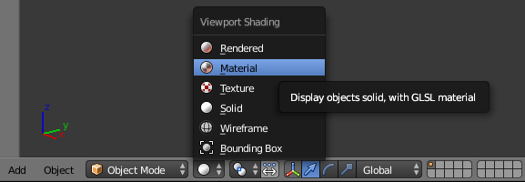
- On the menu bar of the 3D View, click the Viewport Shading button and select Material:
- In the Properties window, click the Render button

- In the Properties window, in the Resolution section, change the resolution from 50% to 100
- Click Sampling to expand it
- Change the Render value from 128 to 500
- In the Properties window, click the World button
- In the Properties window, click Use Nodes
- Click the dark-gray button
 on the right side of Color
- In the menu that appears, click RGB
- Click the horizontal bar below the color wheel, click RGB, and set the color as follows:
R: .658
G: .886
B: 1
- In the work area, right-click the available light to select it
- In the Properties window, click the Object Data button

- In the Lamp section, click Sun
- Click Use Nodes
- Click the value of Strength to select it
- Type 10 and press Enter
- On the Tools window, click the Create tab
- Click Plane
- In the Add Plane section below the Tools window, change the following values:
Radius:    40
Location - Z: .01
- Right-click the left border of the Properties window and click Split Area
- Click somewhere in the middle of the half side of the screen
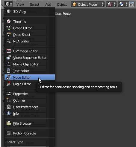
- Click the bottom in the bottom-left section of the new window and click Node Editor:
- In the Properties window, click the Material button

- In the Material section of the Properties window, click the New button
- Click the dark-gray button on the right side of Color and click RGB
- Click the horizontal bar below the color wheel and click Hex
- Set the color value as c0b19e
- In the 3D View, right-click the house (the cylinder) to select it
- On the menu bar of the Node Editor, click the New button
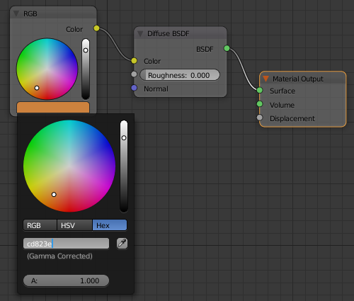
- On the menu bar of the Node Editor, click Add -> Input -> RGB
- Position the window on the left side of the Diffuse BSDF window and click
- Draw a line from the yellow button of RGB to the yellow button of Diffuse BSDF
- In the RGB window, click the horizontal bar below the color wheel and click Hex
- Set the color value as cd823e
- Right-click the bottom side of the border between the Node Editor and the 3D View
- Click Join Area
- Click inside the Node Editor to close it
- Position the mouse in the work area and, to display the camera view, in the Numeric Pad, press 0
- Press N to display the Properties Region
- In the Properties Region, click the Lock Camera to View check box
- Use the mouse to position the view so you can see the house and roof:

- In the Properties Region, click the Lock Camera to View to remove the check mark
- Press N to close the Properties Region
- To preview the result, on the top menu, click Render -> Render Image:

- After viewing the result, press Esc to return to the 3D View
- In the top menu bar, click the button on the left side of Default and click Compositing
An Image as Texture
Normally, when you model an object, you can paint it with a color of your choice. If you want an object to appear closer to real world, you can paint it with an actual picture. This is like gluing a picture on the surface of an object. To support this, Cycles Render provides a texture named Image Texture.
To apply a picture to an object in the Properties window, use the dark-gray button of the Color button and select Image Texture, and then select a picture.
To apply a picture to an object using the Node Editor, add an Image Texture window, specify its file using the Open button, then connect its yellow button (Color) to the yellow button of the Diffuse BSDF window.
In both cases, you should unwrap the object.
 Practical Learning: Applying an Image as Texture
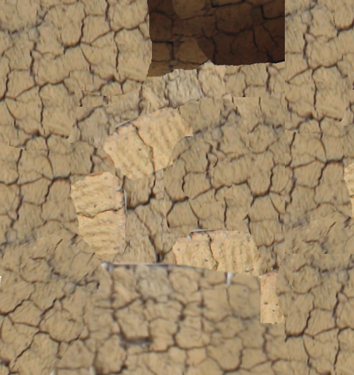
- Save the following pictures to your hard drive:
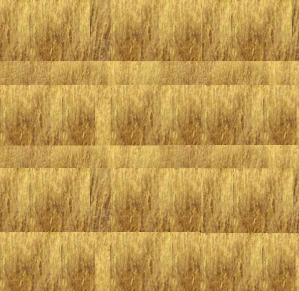
- In the 3D View (in the bottom-right side, marked Camera Persp), right-click the roof of the house to select it:

- In the Properties window, click the Material button

- On the menu bar of the Node Editor, click Use Nodes:
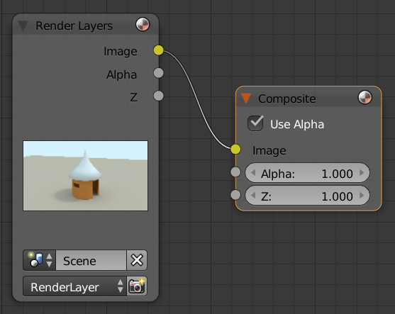
- In the Properties window, click the New button
- In the Properties window, click the dark-gray button on the right side of the Color button
- On the menu that appears, click Image Texture

- In the Properties window, click the Open button
- Locate the Straw.png picture, select it, and click Open Image
- Position the mouse in the 3D View (in the bottom-right side, marked Camera Persp) and press Tab to work in Edit Mode
- Press A twice to select all edges
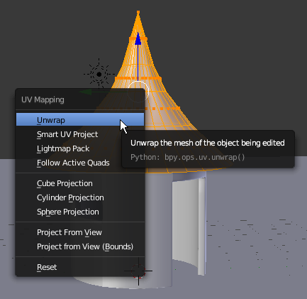
- Press U to display the UV Mapping menu
- In the menu that appears, click Unwrap
- On the menu bar of the UV/Image Editor (in the bottom-left side of the screen), click the button on the left side of New and click Straw.png
- In the Top menu, click the button on the left side of Compositing and select Default
- On the main menu, click Render and click Renber image:

- After viewing the result, press Esc
- On the main menu, click the button on the left side of Default and click Compositing
- Position the mouse in the 3D View (in the bottom-right side, marked Camera Persp) and press Tab to display the roof in Object Mode
A Texture for a Design Mask
One of the ways you can use a texture is to apply its pattern to a color. In this case, you are not interested in the colors on a picture or the actual objects on that picture. Instead, what you want is the design pattern or patterns applied to the object(s). That design would be applied to the color of your object. For this reason, you should (must) use the Node Editor to apply the design.
To let you apply a (texture) design to the color of an object, Cycles Render provides a property named Displacement. This characteristic is used on the output window. The Displacement property is used to indicate that the color would be displaced on the surface of the object using the pattern of the designed texture.
 Practical Learning: Introducing Textures
- In the 3D View (in the bottom-right side, marked Camera Persp), right-click the house to select it
- On the menu bar of the Node Editor, click the Shader Nodes button
 (on the right side of the Node menu item)
- Position the mouse in the Node Editor and press Shift + A -> Texture -> Image Texture
- Position the window below the Diffuse BSDF window and click
- In the Image Texture window, click the Open button
- Locate the Mud.png picture, click it, and click Open Image
- Locate the Mud.png file, select it, and click Open Image
- In the Node Editor, drag the yellow button from the Image Texture window and drop it on the gray button of Displacement in Material Output:

- Position the mouse in the 3D View window in the bottom-right side (marked Camera Persp) and press Tab to display the house in Edit Mode
- Press A twice to select all faces of the house
- With the mouse still positioned in the 3D View (may be marked Camera Persp) window, press U to unwrap
- In the menu that appears, click Smart UV Project
- In the dialog box that displays, click OK
- On the menu bar of the UV/Image Editor, click the button on the left side of Straw.png and click the Mud.png file you had selected
- On the top menu bar, click the button on the left side of Compositing and and click Default
- Position the mouse in the work area and press Tab to display the house (cylinder) in Object Mode
- In the Properties window, click the Render tab

- In the Render section, click the Render button:


- After viewing the result, press Esc to return to the default view


![]() Practical Learning: Setting Up the Scene
Practical Learning: Setting Up the Scene


![]() Practical Learning: Modeling the Roof
Practical Learning: Modeling the Roof


![]() Practical Learning: Putting the Scene Together
Practical Learning: Putting the Scene Together


![]() Practical Learning: Applying an Image as Texture
Practical Learning: Applying an Image as Texture


![]() Practical Learning: Introducing Textures
Practical Learning: Introducing Textures