 |
Blender Materials: Anisotropic |
|
Introduction
 Practical Learning: Starting the Project
- Start Blender
- In the Properties window, click the Object button

- In the Outliner, click the Restrict Viewport Visibility button (the eye) on the right side of Lamp to hide it
- In the Outliner, click the Restrict Rendering button (the camera) on the right side of Lamp
 Practical Learning: Starting a Refrigerator
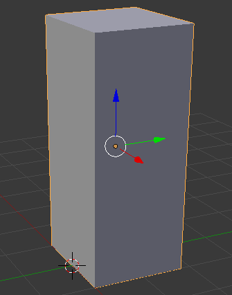
- The default cube should be selected. If you have a doubt, right-click it.
In the Object section of the Properties window, click Cube to select the name
- Type Refrigerator Body and press Enter
- In the Transform section, change the following values:
Location - Y: .9
		     Z: 2.25
Scale    - Y: .9
		     Z: 2.25
 Practical Learning: Modeling a Refrigerator Door
- Position the mouse in the work area and, in the Numeric Pad, press 5 to display the orthogonal view
- To start a door of the refrigerator, on the Tools menu, click Create
- Click Circle
- In trhe Add Circle section below the Tools window, set the Vertices value to 64
- In the Object section of the Properties window, change the following values:
Name:      Refrigerator Bottom Door
Location - X: 0
		     Y: -10
		     Z: .15
Scale    - X: 1.625
		     Y: .215
- On the menu bar of the 3D View, click Object Mode and click Edit Mode
- On the menu bar of the 3D View, click View and click Top to display the top view
- Zoom in the circle to see as much as possible of it
- Press A to deselect everything
- Press B to box-select
- Draw a rectangle that covers the left vertices as follows:

- Press B and select the equivalent vertices on the other side of the circle as follows:

- Press B and select the remaining vertices on the top side of the circle as follows:

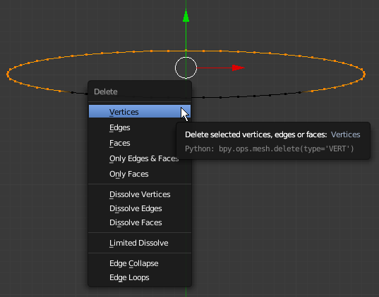
- Press X to delete
- On the menu that appears, click Vertices:
- Right-click the last vertex on one side
- Press and hold Shift
- Right-click the last vertex on the other side
- Release Shift:

- Press S to mov the vertices
- Type .97 and press Enter
- Press E to extrude
- Press Y to extrude deeply
- Type .1 and press Enter

- Press F to join both vertices to create an edge and press Enter
- Press A twice to select all vertices
- Press E to extrude the shape
- Press Z to extrude vertically
- Type 1.5 and press Enter
- Position the mouse on the back face and press Ctrl + R to get a vertical line (don't click). Here is an example:
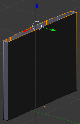
- Type 13 and press Enter twice:
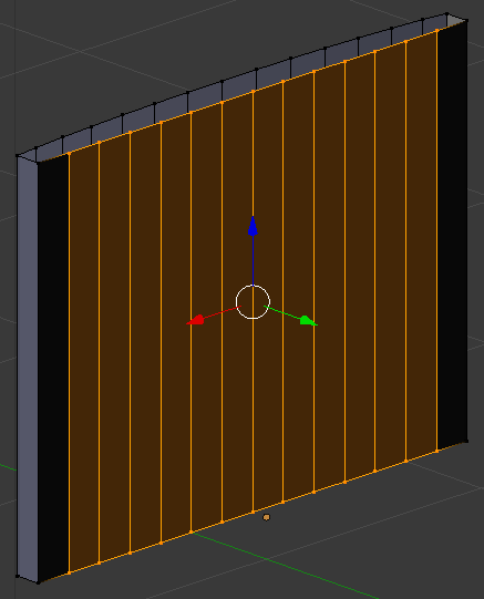
- On the menu bar of the 3D-View, click the Edge Select button

- Right-click the horizontal edge on one end as follows:
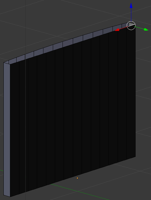
- Press and hold Shift
- Right-click the opposing edge
- Release Shift:
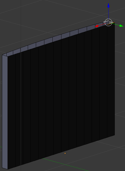
- Press F to create a face:
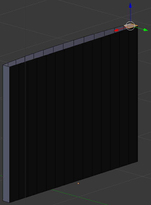
- In the same way, create faces of each combination of oppositing edges:
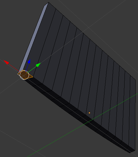
- On the menu bar of the 3D View, click Edit Mode and click Object Mode:
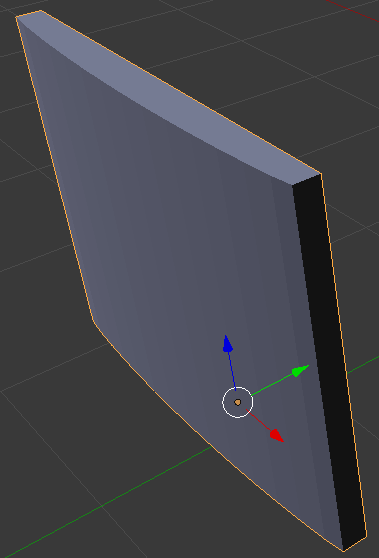
- In the Properties window, click the Modifiers button
- Click Add Modifier and, in the menu that appears, click Subdivision Surface
- Set the View value to 2
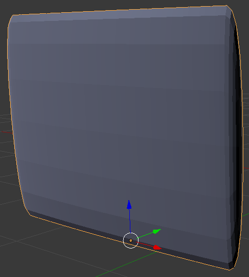
- On the menu bar of the 3D View, click Object Mode and click Edit Mode
- Press Ctrl + R to get a horizontal cut:
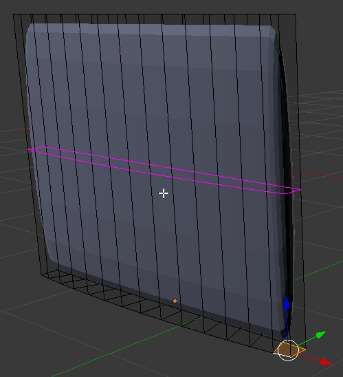
- Move the mouse up and move the line as close as possible to the top border:
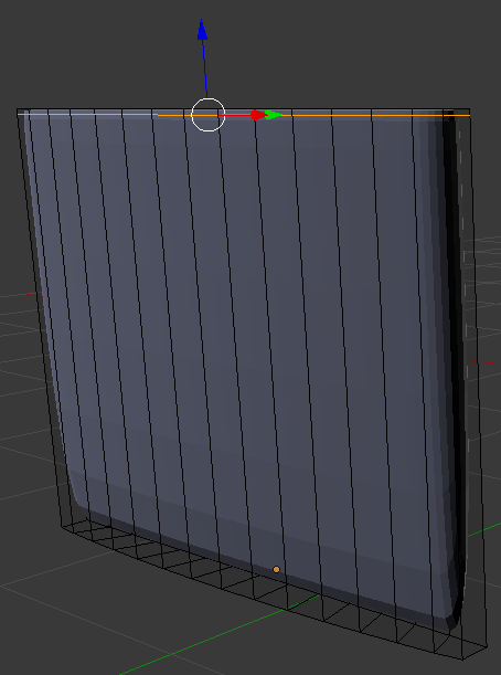
- In the same way, create a horizontal cut and move it close to the bottom border:
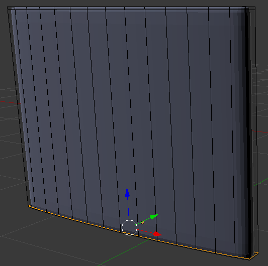
- Position the mouse between the left border and the second edge from left toreate a vertical cut and click once:
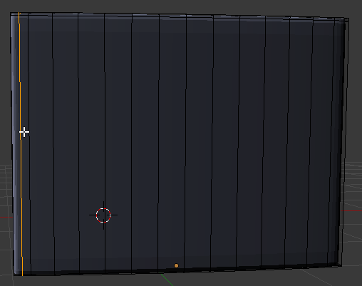
- Then move its line close to the left border
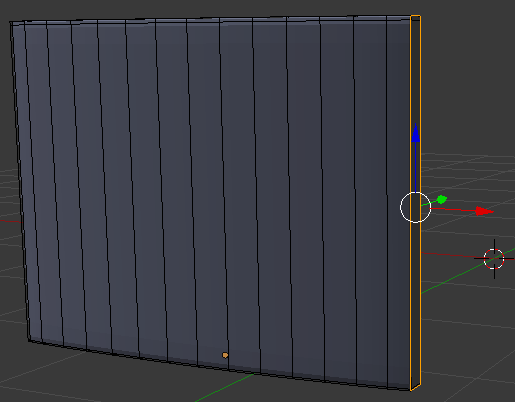
- In the same way, create a vertical cut between the right border of the second cut from right. Move it close to the right border. Here is an example:
- On the menu bar of the 3D View, click Edit Mode and click Object Mode
- In the Properties window, click Apply
- In the Tools window, click the Tools tab
- In the Shadding section, click Smooth
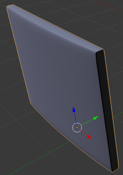
- On the Numeric pad, press 3 to access the right view.
Make sure you are in orthogonal view, which is done by pressing 5 in the Numeric Pad)
- Move the door and position it close to the refrigerator
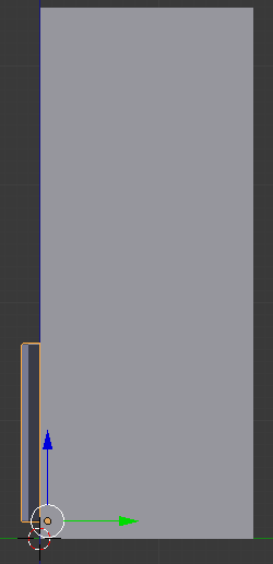
 Practical Learning: Creating the Main Door of the Refrigerator
- In the Properties window, click the Object button

- While the bottom door is still selected, press Alt + D to duplicate and press Enter
- In the Properties window, change the following values:
Name:         Refrigerator Top Door
Location - Z: 1.725
Scale    - Z: 1.85
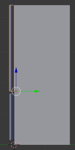
 Practical Learning: Creating Door Handles
- On the Tools window, click Create
- In the Create tab of the Tools window, click Circle
- In the Add Circle section below the Tools window, click the value of Vertices
- Type 48 and press Enter
- In the Properties window, change the following values:
Name:      Refrigerator Bottom Door Handle
Location - Y: -2.18
		     Z: 1.45
Scale    - X: 3
- On the menu bar of the 3D View, click View -> Top
- On the menu bar of the 3D View, click Object Mode and click Edit Mode
- Press F to create a face that covers the circle
- Press E to extrude and press Enter
- Press S to resize
- Type .98 and press Enter
- While the middle face is selected (if it is not, right-click the middle face to select it), press X
- In the menu that appears, click Faces
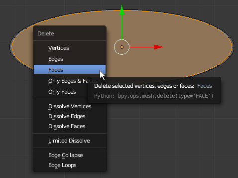
- On the menu bar of the 3D-View, click the Face Select button

- Right-click the middle face to select it
- Press X and, in the menu that appears, click Faces
- Press B to prepare to box-select
- Draw a rectangle that covers the lower part of the shape as follows (there is no need for precision, myou can make corrections later):

- Press X to delete
- In the menu that appears, click Only Edges & Faces
- Press A to select all edges
- Use the red and green arrows to move the shape and position it in fron of the refrigerator:
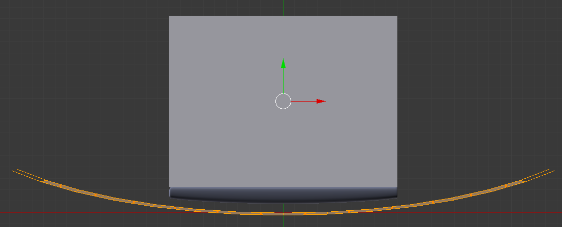
- Zoom in to see as much as possible of the shape
- By using the Face Select button
 and the Edge Select button
  , by right-clicking, select some faces and edges, then delete them as follows:

- Right-click an ending edge to select it. Here is an example:
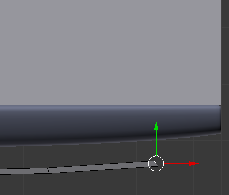
- Press E to extrudee and move the mouse close to the door of the refrigerator:
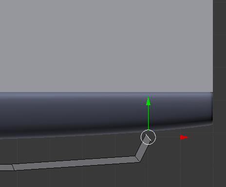
- Select the edge of the other side, press E to extrude, and extrude it close to the door:

- In the Numeric Pad, press 1 to access tje front view
- Press A twice to select all faces
- Press E to extrude
- Type .085 and press Enter:
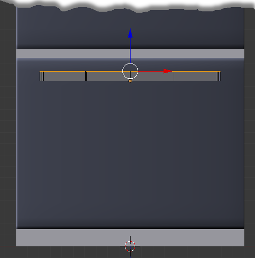
- On the menu bar of the 3D View, click Edit Mode and click Object Mode
- On the menu bar of the 3D View, click View and click Top
- Move the handle to the refrigerator so it touches the door
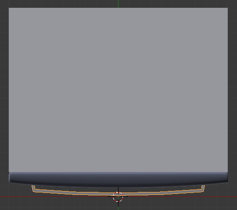
- In the Tools window, click the Tools tab
- In the Tools section, click Smooth
- Position the mouse in the work area, press Alt + D and press Enter
- In the Properties window, change the following values:
Name:      Refrigerator Top Door Handle
Location - X: -.85
	   	     Z: 3.15
Rotation - Y: 90
Sace     - X: 4.25

 Practical Learning: Creating a Kitchen Cabinet - Bottom-Left
- In the Create section of the Tools window, click Cube
- In the Properties window, change the following values:
Name:      Cabinets Base
Location - X: 5.045
		     Y: .95
	         Z: .05
Scale  -   X: 4.025
			 Y: .85
           Z: .05

- On the menu bar of the 3D-View, click Add -> Mesh -> Cube
- In the Object tab of the Properties window, change the following values:
Name:      Cabinet - Bottom-Left
Location - X: 2.03
	         Y: .9
	         Z: .8
Scale    - Y: .9
	         Z: .725

 Practical Learning: Modeling a Cabinet Drawer - Left
- Position the mouse in the work area, press Alt + D and press Enter
- In the Object tab of the Properties window, change the following values:
Location - Z: 1.73
Scale    - Z: .2

 Practical Learning: Modeling a Top Cabinet - Left
- Position the mouse in the work area, press Alt + D and press Enter
- In the Object tab of the Properties window, change the following values:
Location - Y: 1.2
		     Z: 4.5
Scale    - Y: .6
		     Z: .85

 Practical Learning: Modeling a Cabinet Door - Top-Left
- Position the mouse in the work area, press Alt + D and press Enter
- In the Object tab of the Properties window, change the following values:
Location - X: 2.03
		     Y: .54
		     Z: 4.5
Scale    - Y: .05
		     Z: .85
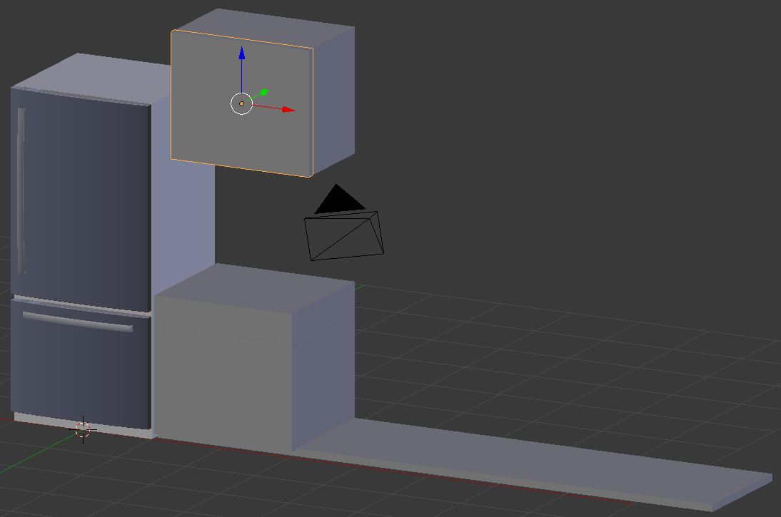
 Practical Learning: Modeling a Kitchen Counter - Left
- On the menu bar of the 3D-View, click Add -> Mesh -> Cube
- In the Object tab of the Properties window, change the following values:
Name:      Kitchen Counter - Left
Location - X: 2.03
		     Y: .9
		     Z: 2
Scale    - Y: .9
		     Z: .05

- Press Tab to display the cube in Edit Mode
- Press Ctrl + R on the cube and make sure you get a cut parallel to the back face of the cube:
- Click twice to accept the cut
- Press G to move the cut
- Press Y to move along that axis
- Type .775 and press Enter
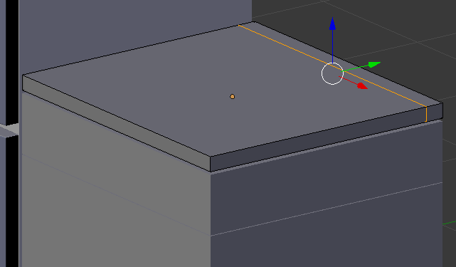
- Position the mouse in the small face and press Ctrl + R to get a cut horizontal to the existing one
- Click twice to confirm the cut
- Press G to move the cut
- Press Y to move along that axis
- Type -.025 and press Enter:
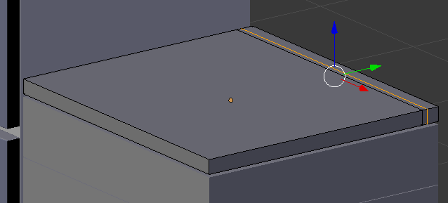
- Press Ctrl + Tab and, in the menu that appears, click Face
- Right-click the right small face to select it:
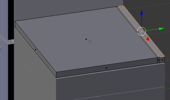
- Press G to move the face
- Press Z to move up
- Type .05 and press Enter:
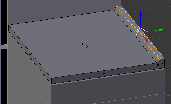
- Press E to extrude
- Type .25 and press Enter:
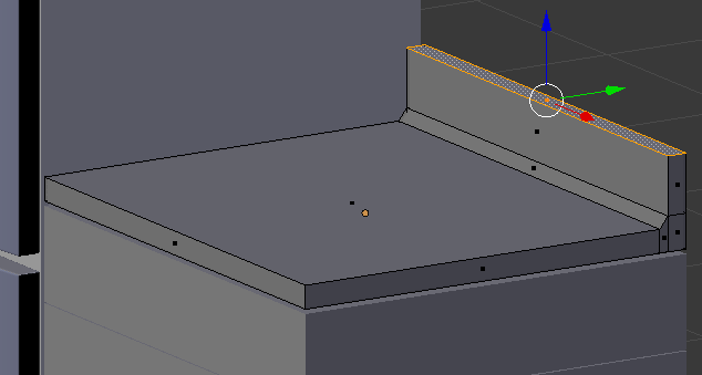
- Press Tab to display the counter in Object Mode:

 Practical Learning: Modeling a Cabinet Handle
- On the menu bar of the 3D-View, click Add -> Mesh -> Torus
- In the Add Torus section below the Tools window, change the following values:
Major Radius: .25
Minor	Radius: .01
- In the Transform tab of the Properties window, change the following values:
Name:      Cabinet Door Handle - Vertical Left
Location - X: 2.9
		     Y: -4
		     Z: 1.15
Rotation - Y: 90
Scale    - X: 1
		     Y: .25
		     Z: 3
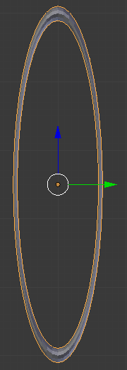
- Zoom in to see as much as possible of the torus
- On the menu bar of the 3D-View, click Object Mode and click Edit Mode
- Press A to deselect everything
- In the Numeric Pad, press 3 to access the right view
- Press Z to display the torus in wireframe
- Press B to box-select
- Draw a rectangle that covers all vertices on the right side:

- Press X to delete
- In the menu that appears, click Faces:

- Press Z to exit from wireframe
- On the menu bar of the 3D View, click Edit Mode and click Object Mode
- In the Tools window, click Tools
- In the Tools tab, click Smooth
- In the Object tab of the Properties window, in the Location section, change the Y value to 0 and press Enter:
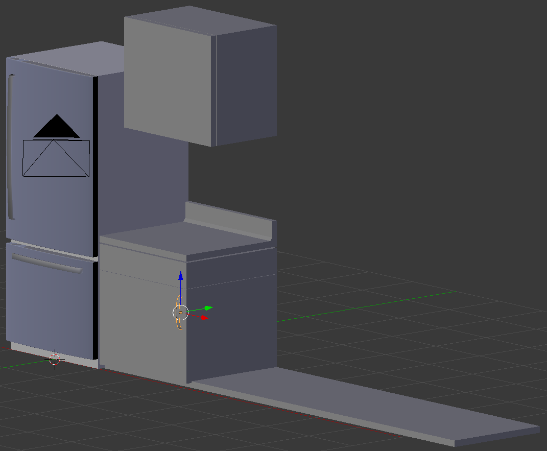
 Practical Learning: Creating a Cabinet Handle - Horizontal Bottom-Left
- While the handle is still selected, press Alt + D and press Enter
- In the Object tab of the Properties window, change the following values:
Name:      Cabinet Door Handle - Top-Left
Location - Y: .5
		     Z: 4

 Practical Learning: Creating a Cabinet Handle - Vertical Bottom-Left
- Right-click the first handle (in the bottom cabinet) to select it
- Press Alt + D and press Enter
- In the Object tab of the Properties window, change the following values:
Location - X: 2
		     Z: 1.825
Rotation - Y: 0

 Practical Learning: Modeling a Kitchen Stove
- On the menu bar of the 3D-View, click Add -> Mesh -> Cube
- In the Object tab of the Properties window, change the following values:
Name:      Stove Oven
Location - X: 4.05
		     Y: .9
		     Z: .925
Scale    - Y: .9
		     Z: .85
- Press Tab to display the cube in Edit Mode
- Press Ctrl + R to get a horizontal cut on the cube, then click twice to accept
- Press G to move the cut
- Press Z to move it vertically
- Type .625 and press Enter:
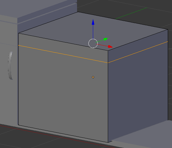
- Press Ctrl + R to get a horizontal cut on the cube, then click twice to accept:
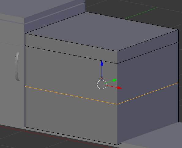
- Press Ctrl + R and create a horizontal cut in the bottom portion of the cube
- Click twice to confirm
- Press G to move the cut
- Press Z to move it vertically
- Type .1 and press Enter::
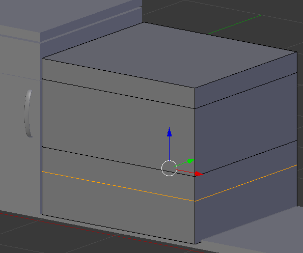
- Press Ctrl + R and create a horizontal cut in the bottom portion of the cube
- Click twice to confirm
- Press G to move the cut
- Press Z to move it vertically
- Type .2 and press Enter:
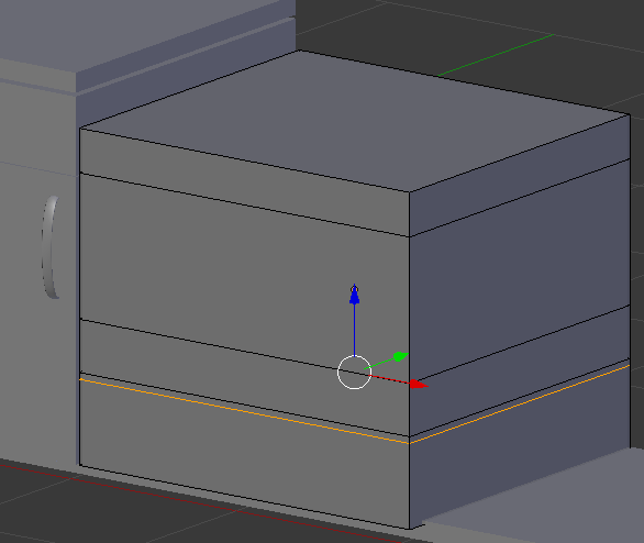
- Press Ctrl + R to get a vertical cut and click twice to confirm
- Press G to move the cut
- Press X to move it vertically
- Type -.85 and press Enter:
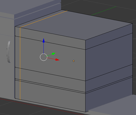
- Press Ctrl + R to get a vertical cut on the right side of the cube and click twice to confirm
- Press G to move the cut
- Press X to move it vertically
- Type .765 and press Enter:
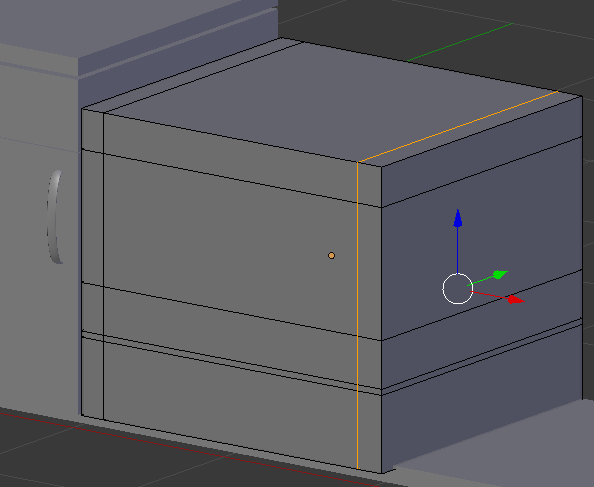
- Press Ctrl + Tab and, in the menu that appears, click Face
- Right-click the large face to select it
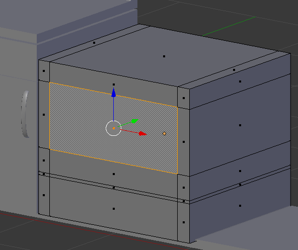
- Press E to extrude and press Enter
- Press G to move
- Press Y to move in that direction
- Type 1.5 and press Enter
- Select the small horizontal faces that were created:
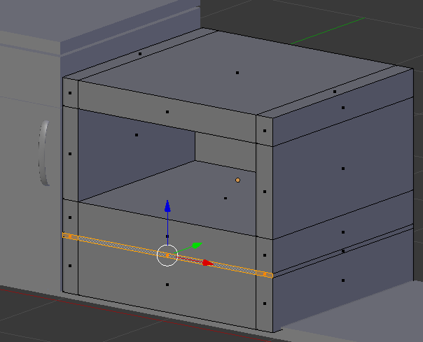
- Press E and press Enter
- Press G to move
- Press Y to move horizontally
- Type .25 and press Enter
- Press Tab to display the stove oven in Object Mode
 Practical Learning: Modeling the Glass of a Stove
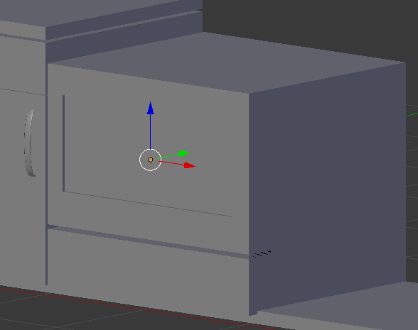
- On the menu bar of the 3D-View, click Add -> Mesh ->Plane
- In the Object tab of the Properties window, change the following values:
Name:       Oven Glass
Location  - X: 4.05
			  Y: .025
			  Z: 1.15
Rotation: - X: 90
Scale     - X: .9
		      Y: .5
 Practical Learning: Creating the Top Oven Handle
- In the Ouliner, click Refrigerator Bottom Door Handle to select it
- Position the mouse in the work area and click Shift + D and press Enter to create a copy
- In the Object tab of the Properties window, change the followiw values:
Name:      Oven Door Handle - Top
Location - X: 4.05
		     Y: -2.05
           Z: 1.615
Scale    - X: 3.25
		     Z: .75

 Practical Learning: Creating the Bottom Oven Handle
- Position the mouse in the work area and click Alt + D and press Enter
- In the Object tab of the Properties window, change the followiw values:
Name:      Oven Door Handle - Bottom
Location - Z: .325

 Practical Learning: Modeling the Top of the Stove
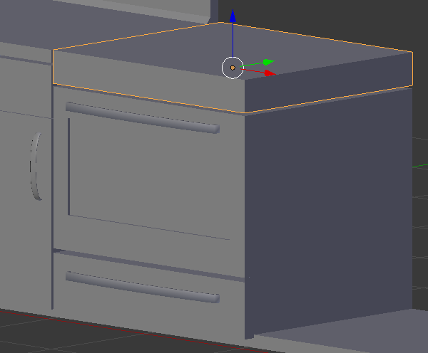
- On the menu bar of the 3D-View, click Add -> Mesh -> Cube
- In the Object tab of the Properties window, change the following values:
Location - X: 4.05
		     Y: .9
		     Z: 1.925
Scale    - Y: .9
		     Z: .125
- Press Tab to display the cube in Edit Mode
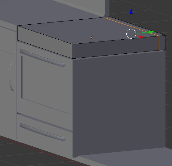
- Press Ctrl + R on the cube and make sure you get a cut parallel to the back face of the cube:
- Click twice to accept the cut
- Press G to move the cut
- Press Y to move along that axis
- Type .775 and press Enter:
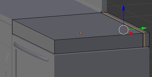
- Position the mouse in the small face and press Ctrl + R to get a cut horizontal to the existing one
- Click twice to get the cut
- Press G to move the cut
- Press Y to move the cut
- Type -.025 and press Enter:
- Press Ctrl + Tab and, in the menu that appears, click Face
- Right-click the small face to select it:
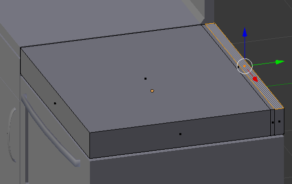
- Press G to move the face
- Press Z to move up
- Type .05 and press Enter
- Press E to extrude
- Type .25 and press Enter:
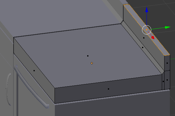
- Press Tab to display the counter in Object Mode:

 Practical Learning: Creating Stove Knobs
- On the Tools window, click Create
- In the Create section, click Cylinder
- In the Add Cylinder section below the Properties window, change the following values:
Vertices: 24
Radius: .065
Depth:  .075
- In the Object section of the Properties, change the following values:
Name:      Stove Knob
Location - X: 3.35
		     Y: -.05
           Z: 1.925
Rotation - X: 90
- In the Tools window, click the Tools tab
- In the Tools tab, click Smooth
- In the Properties window, click the Modifiers button

- Click Add Modifier and click Array
- Change the values as follows:
Count:     6
Relative - X: 2.15
- In the Properties window, click Apply:

- In the Properties window, click the Object button

 Practical Learning: Creating Pots Support
- On the menu bar of the 3D-View, click Add -> Mesh -> Cube
- In the Object tab of the Properties window, change the following values:
Name:      Pot Support
Location - X: 3.625
		     Y: -5
		     Z: 2.07
Scale    - X: .3
		     Y: .3
		     Z: .02
- Position the mouse in the work area and press Tab to display the cube in Edit Mode
- Press Ctrl + Tab and, in the menu that appears, click Face
- Right-click the top face to select it
- Press I to create an inset
- Type .1 and press Enter
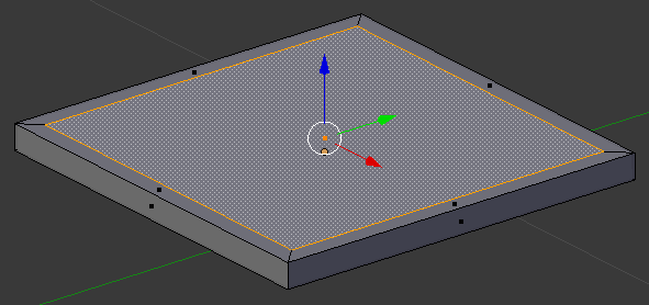
- While the face is still selected, press X to delete
- In the menu that appears, click Faces
- Right-click the inside face to select the back face
- Press I to create an inset
- Type .1 and press Enter
- While the bottom central face is selected, press X to delete
- In the menu that appears, click Faces
- On the menu bar of the 3D-View, click the Edge Select button

- Right-click one of the inside edges. Here is an example:
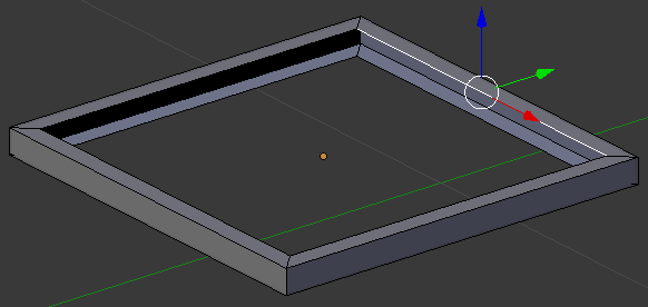
- Press and hold Shift
- Right-click the opposing line to select them both
- Release Shift:
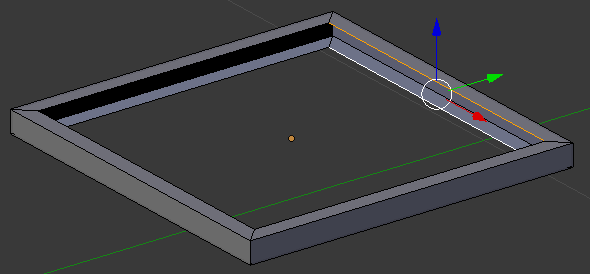
- Press F to create a face
- In the same way, create faces of each combination of opposing edges:
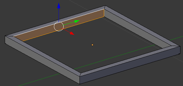
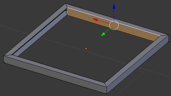
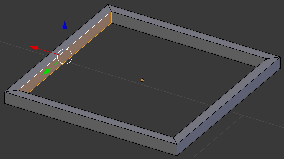
- Position the mouse on one side of the object.
Press Ctrl + R and roll the mouse once to get a double-cut on that side
- Click twice to accept. Here is an example:
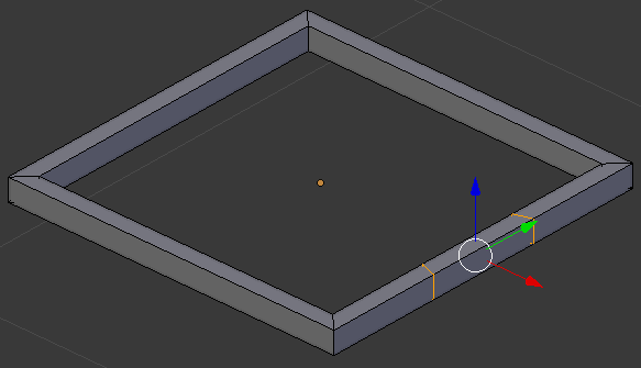
- Press S to move the lines
- To restrict the move, if the cuts are on a green arrow, press Y.
If the cuts are on a red arrow, press X
- Type .2 and press Enter:
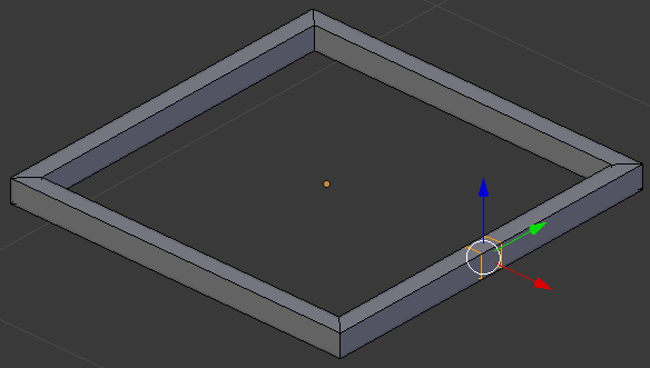
- In the same way, create cuts on the other borders:
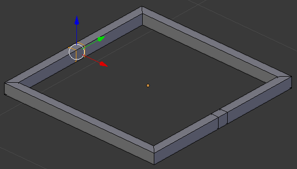
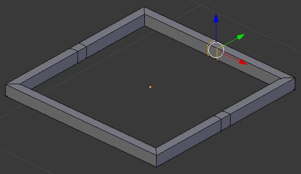
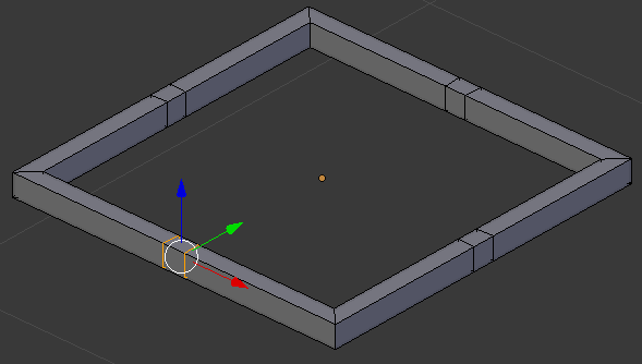
- On the menu bar of the 3D-View, click the Face Select button

- Right-click one of the inside faces that were created. Here is an example:
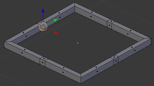
- Press X to delete
- In the menu that appears, click Faces
- In the same way, select and delete all inside small faces:
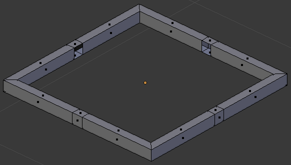
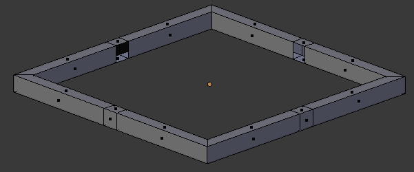
- Select the small top and bottom faces in the middle of each border (right-click one of them to select it, press and hold Shift, right-click each of the others, then release Shift):
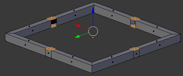
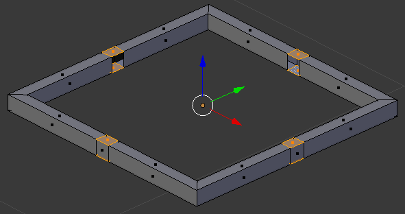
- Press X to delete
- In the menu that appears, click Faces
- Select the middle-back faces that were left (right-click one of them to select it, press and hold Shift, right-click each of the others, then release Shift):
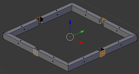
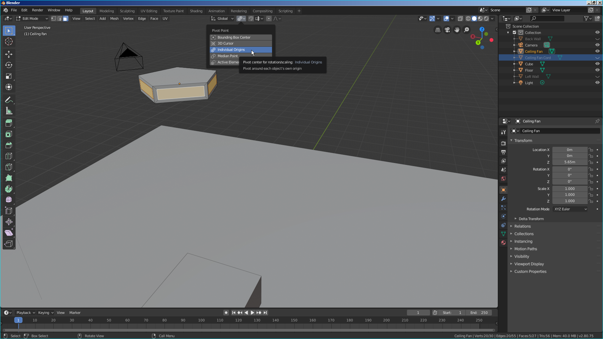
- On the menu bar of the 3D View, click the Pivot button and select Individual Origins:
- Press E to extrude
- Type .01
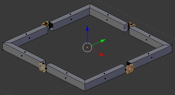
- Press Enter
- Select and delete all four faces each of the faces that were created. When you finish, each face should be standing by itself:
- Select the four faces that were left standing (right-click one of them to select it, press and hold Shift, right-click each of the others, then release Shift):
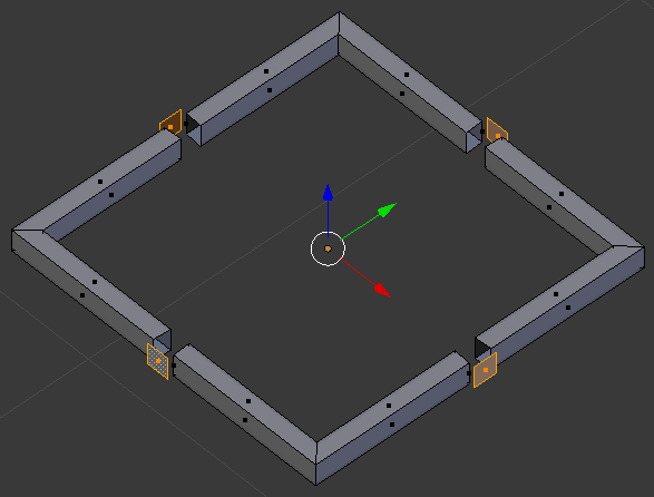
- Press S to resize each face
- Type 1.5 and press Enter:
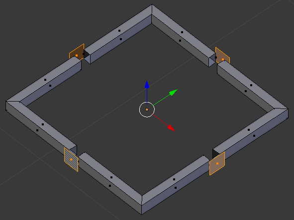
- Press E to extrude
- Type -.225 and press Enter:
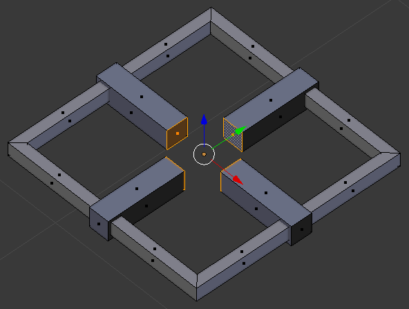
- Press S to rerize the faces
- Type .5 and press Enter:
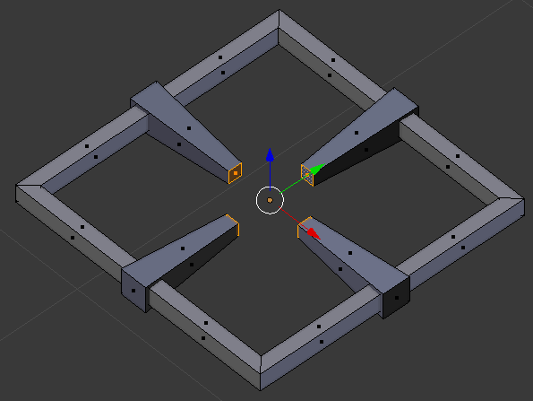
- Press G to move the faces
- Press Z to move them vertically
- Type .01 and press Enter
- In the menu bar of the 3D View, click Edit Mode and click Object Mode
- In the Object tab of the Properties window, change the following value:
Location - Y: .5
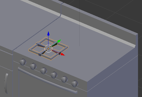
- Press Alt + D and press Enter to copy the object
- In Object tab of the Properties window, change the following value:
Location - Y: 1.225
- Position the mouse in the work area. Press Alt + D and press Enter
- In the Object tab of the Properties window, change the following value:
Location - X: 4.5
- Position the mouse in the work area. Press Alt + D and press Enter
- In the Object tab of the Properties window, change the following value:
Location - Y: .5
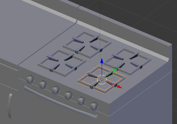
 Practical Learning: Creating a Kitchen Stove Ventilator
- In the Properties window, click the Object button

- On the menu bar of the 3D-View, click Add -> Mesh -> Cube
- In the Object tab of the Properties window, change the following values:
Name:      Stove Ventilator
Location - X: 4.05
		 	 Y: 1.15
		 	 Z: 4.5
Scale    - X: 1
		     Y: .65
		     Z: .85
- On the menu bar of the 3D view, click Object Mode and click Edit Mode
- Press Ctrl + Tab and, in the menu that appears, click Face
- Right-click the bottom face to select it
- Press X to remove
- In the menu that appears, click Faces
- Position the mouse on the cube, press Ctrl + R and make sure you get a horizontal line/cut
- Click twice to confirm the cut
- Press S to resize
- Type .5 and press Enter

- On the menu bar of the 3D-View, click the Face Select button

- Right-click the top face to select it
- Press S to resize
- Type .5 and press Enter:

- Press and hold Alt
- Right-click one of the vertical faces in the top part of the object
- Release Alt:

- Press G to move
- Press Y to move horizontally
- Type .315 and press Enter:

- Press Tab to display the ventilator in Object Mode
- Press A to deselect everything
 Practical Learning: Extending the Kitchen Cabinets
- In the Numeric Pad, press 1 to show the front view
- Press Z to display the shapes in wireframe
- Press B to box-select
- Draw a rectangle that covers the objects between the refrigerator and stove:


- Press Z to exit from wireframe
- Press Alt + D to duplicate the objects
- Press X to move the objects to the right
- Type 4.03 and press Enter:

- Press Alt + D to duplicate the objects
- Press X to move the objects to the right
- Type 2.01 and press Enter:

- Right-click the top right counter to select it:

- Press X to remove it
- In the menu that appears, click Delete
- Right-click the new top-right counter to select it
- In the Object tab of the Properties window, change the following values
Name:      Kitchen Counter - Right
Location - X: 7.065
Scale    - X: 2.005

- In the Numeric Pad, click 1 to access the front view
- Move the right vertical handles to the left of their respective cabinets:
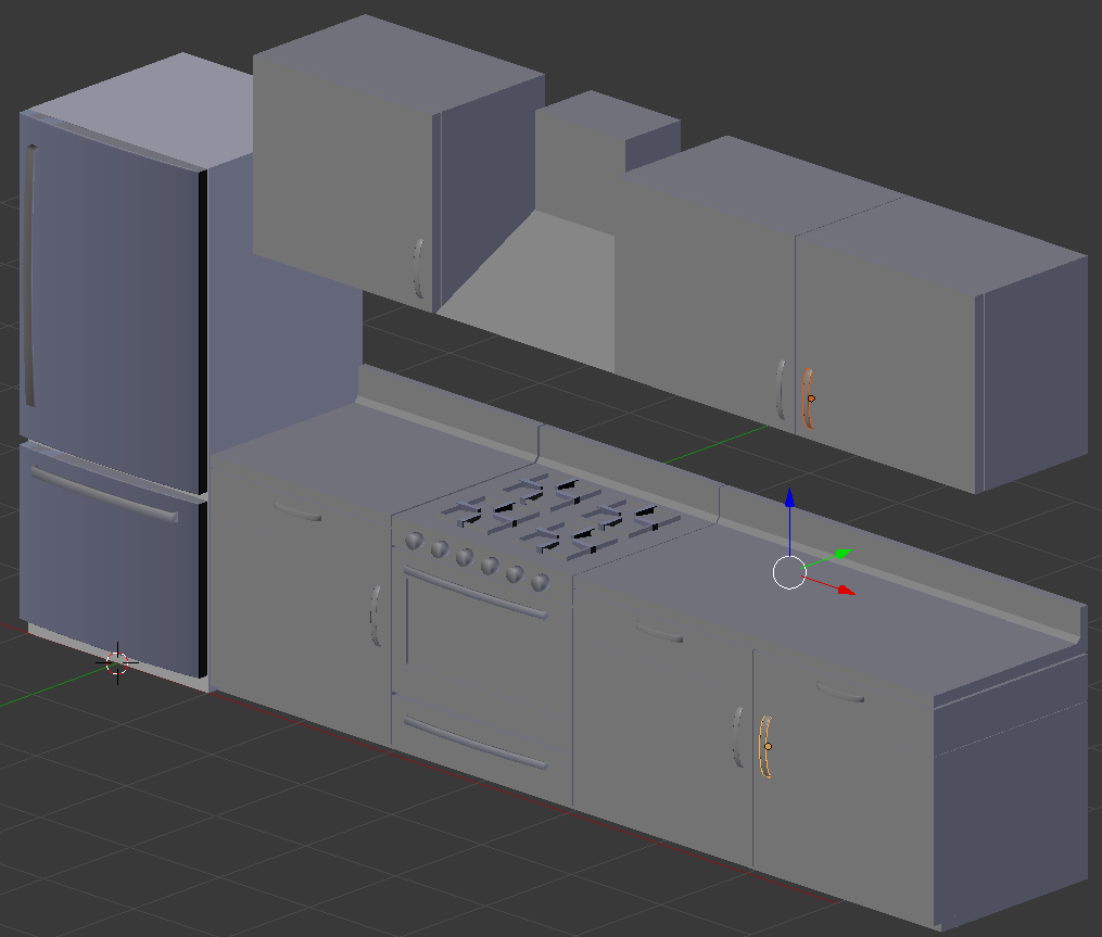
 Practical Learning: Modeling a Utensils Holder
- On the Tools window, click Create
- In the Create tab, click Cube
- In the Object tab of the Properties window, change the following values:
Name:      Utensils Holder
Location - X: 6.5
		     Y: -10
           Z: 2.102
Scale    - X: 1.25
		     Y: .2
           Z: .05
- On the menu bar of the 3D View, click Object Mode and click Edit Mode
- Press Ctrl + R to get a cut parallel to the red arrow (the X axis)
- Roll the mouse once to get two cuts
- Click twice to confirm
- Press S to move the lines
- Press Y to move them apart
- Type 1.75 and press Enter
- On the menu bar of the 3D-View, click the Edge Select button

- Right-click one of the long borders to select it
- Press and hold Shift
- Right-click the other long borders
- Release Shift:
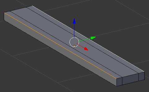
- Press G to move the borders
- Press Z to move them up
- Type .025 and press Enter:
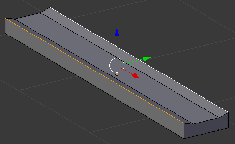
- Press Ctrl + R to get a cut parallel to the red green arrow (the Y axis)
- Roll the mouse once to get two cuts
- Click twice to confirm
- Press S to move the lines
- Press X to move them apart
- Type 2.5 and press Enter:
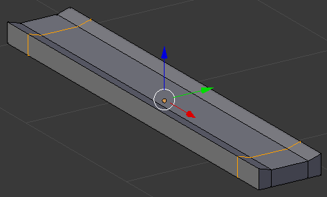
- Select the middle edge on each short border:
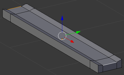
- Press G to move the borders
- Press Z to move them up
- Type .1 and press Enter
- On the menu bar of the 3D View, click Edit Mode and click Object Mode
- In the Object tab of the Properties window, change the following value:
Location - Y: .7

 Practical Learning: Modeling a Steel Pot
- In the Tools window, click Create and click UV Sphere
- In the Add UV Sphere section below the Tools window, change the following values:
Segments: 48
Rings:    48
- In the Object tab of the Properties window, change the following values:
Name:      Stainless Steel Pot
Location - X: 3.625
			 Y: -10
           Z: 2.115
Scale    - X:  .45
			 Y:  .45
           Z:  .1
- In the Numeric Pad, press 3 to display a horizontal view of the sphere
- On the menu bar of the 3D View, click Object Mode and click Edit Mode
- On the menu bar of the 3D-View, click the Edge Select button

- Press A to deselect everything
- Press Z to display the sphere in wireframe
- Press B to box-select
- Draw a rectangle that covers half or 2/3 of the bottom half of the sphere:

- Press X to delete
- In the menu that appears, click Faces:
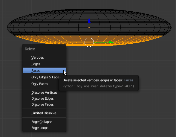
- Press B to box-select
- Draw a rectangle that covers the top half of the sphere:

- Press X to delete
- In the menu that appears, click Faces
- Press and hold Alt
- Right-click one of the top edges
- Release Alt:

- Press Z to exit the wireframe
- Press E to extrude
- Press Z to extrude vertically
- Type .685 and press Enter:
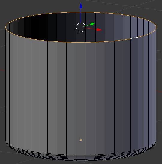
- Press E to extrude
- Press Z to extrude vertically
- Type .02 and press Enter
- Press S to resize the selected top part
- Type 1.02 and press Enter:
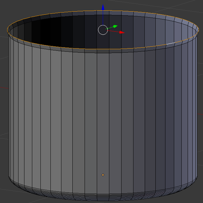
- Press E to extrude
- Press Z to extrude vertically
- Type .02 and press Enter
- Press S to resize the selected top part
- Type 1.05 and press Enter:
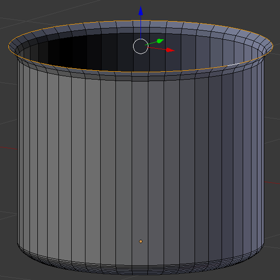
- On the menu bar of the 3D View, click Edit Mode and click Object Mode
- In the Properties window, click the Modifiers button

- Click Add Modifier and click Solidify:
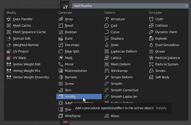
- Click the Thickness value, type .035 and press Enter
- Click Apply:
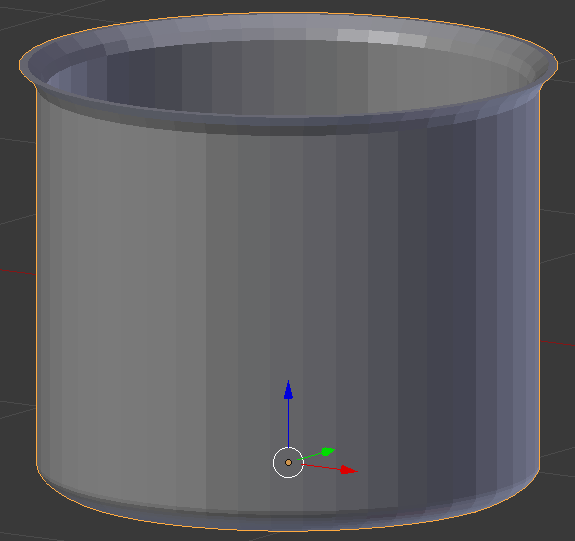
- In the Modifiers section of the Properties window, click Add Modifier and click Subdivision Surface
- Set the View value to 2
- On the menu bar of the 3D View, click Object Mode and click Edit Mode
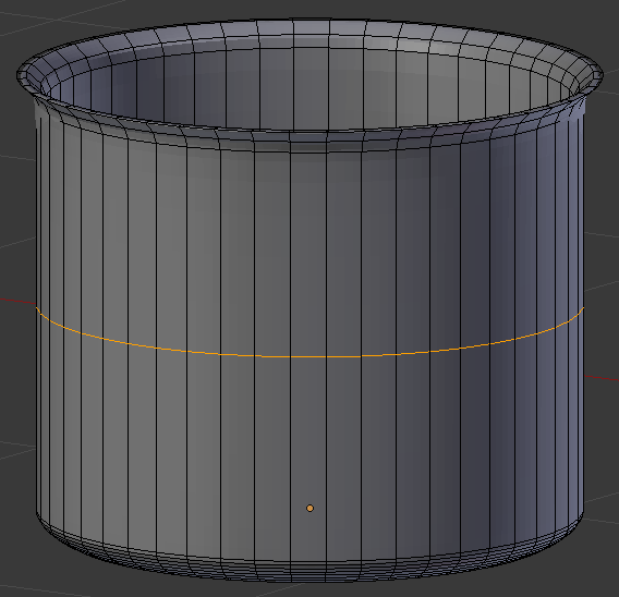
- Position the mouse on the pot. Press Ctrl + R to get a horizontal cut and click once to accept the cut:
- Move the line up and position it as close as possible to the top line:
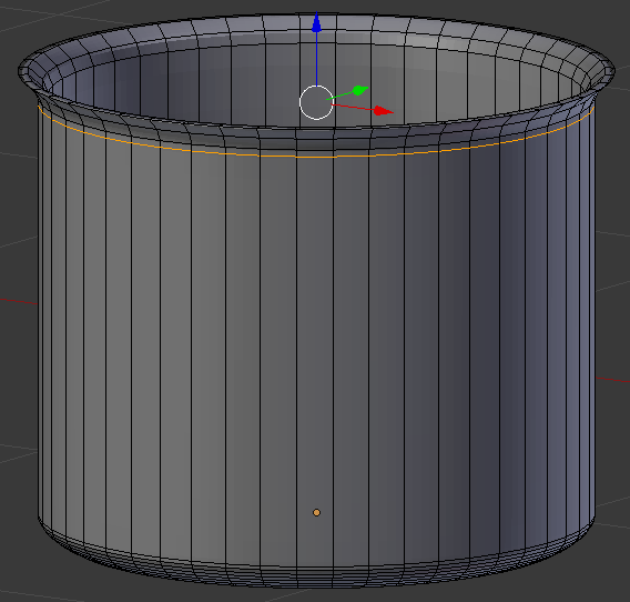
- Using Ctrl + R, create another horizontal cut and move it down to the bottom curve:
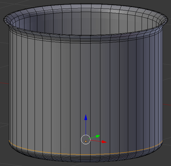
- On the menu bar of the 3D View, click Edit Mode and click Object Mode
- In the Modifiers section of the Properties window, click Apply:
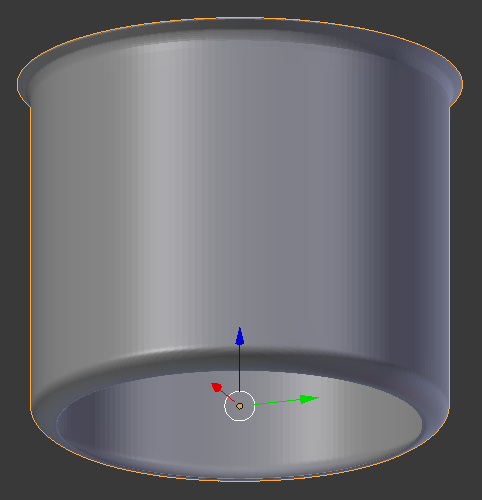
- On the menu bar of the 3D View, click Object Mode and click Edit Mode
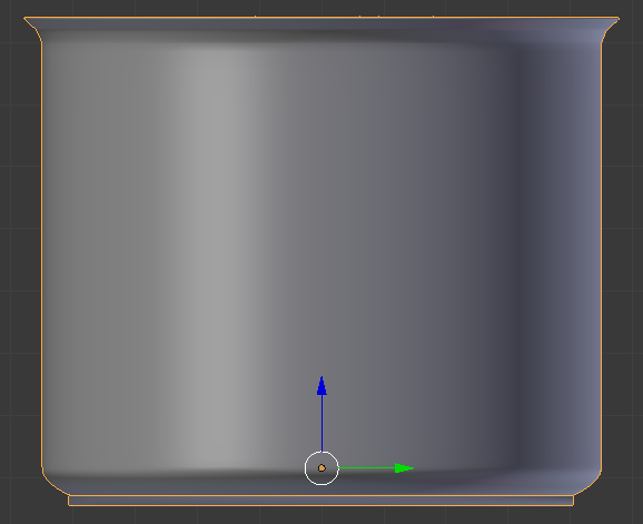
- In the Numeric Pad, press 3 to access a side view of the pot
- Click an empty area somewhere below the pot. Here is an example:
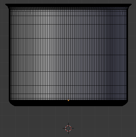
- In the Create tab of the Tools window, click Cylinder
- In the Add Cylinder section below the Tools window, change the following values:
Vertices: 48
Radius:   .405
Depth:    .015
- Use the axes arrows (red, blue, and green) to position the base on the bottom side of the pot:
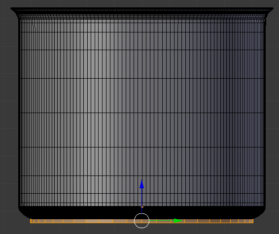
- On the menu bar of the 3D View, click Edit Mode and click Object Mode
- In the Tools window, click the Tools tab and click Smooth:
- In the Properties window, click the Object button

- Change the following values:
Location - X: 3.625
			 Y: .501
           Z: 2.165

 Practical Learning: Modeling another Pot
- Position the mouse in the work area, press Shift + D and press Enter
- In the Object tab of the Properties window, change the following values:
Name:      Regular Pot
Location - X: 2.25
		     Y: .75
           Z: 2.1
Scale    - X: .4
			 Y: .4
           Z: .07

 Practical Learning: Modeling One More Pot
- Right-click the first pot that was created
- Press Shift + D and press Enter
- In the Object tab of the Properties window, change the following values:
Name:      Small Pot
Location - X: 4.5
           Z: 2.13
Scale    - X: .285
			 Y: .285
           Z: .055

 Practical Learning: Creating a Skillet
- On the menu bar of the 3D View, click Add -> Mesh -> Cone
- In the Add Cone section below the Tools window, change the following values:
Vertices: 64
Radius 1: .55
Radius 2: .5
Depth:    .15
Base Fill Type: Triangle Fan
Location - X: 5.85
		     Y: .7
           Z: 2.7
Rotation - X: 90

- In the Object tab of the Properties window, click Cone to select the name
- Type Egg Skillet and press Enter:
 Practical Learning: Creating another Skillet
- Position the mouse in the work area, press Shift + D to copy and press Enter
- In the Object tab of the Properties window, change the following value:
Name:	Heat Skillet
Location - X: 7.15

 Practical Learning: Creating a Kitchen
- On the menu bar of the 3D-View, click Add -> Mesh -> Plane
- In the Object tab of the Properties window, change the following values:
Name:      Floor
Location - X: 4.25
		     Y: -2.75
		     Z: .01
Scale    - X: 7
		     Y: 5
- On the menu bar of the 3D-View, click Add -> Mesh -> Plane
- In the Object tab of the Properties window, change the following values:
Name:      Left Wall
Location - X: -2
		     Y: -1.25
		     Z: 3.5
Rotation - Y: 90
Scale    - X: 4
		     Y: 3.5
- On the menu bar of the 3D-View, click Add -> Mesh -> Plane
- In the Object tab of the Properties window, change the following values:
Name:      Back Wall
Location - X: 4
		     Y: 1.85
		     Z: 3.25
Rotation - X: 90
Scale    - X: 7
		     Y: 3.5

- Position the mouse on the work area and, in the Numeric Pad, press 0 to display the camera view
- Press N to display the Properties Region
- In the Properties Region, click Lock Camera to View to put a check box on it
- Use the mouse and keyboard to display the view any way you want. Here is an example::

- In the Properties Region, click Lock Camera to View to remove the check mark
- Press N to close the Properties Region
 Practical Learning: Applying Introductory Materials
- On the top menu bar, click Blender Render and click Cycles Render
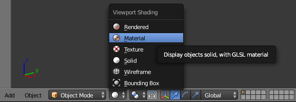
- On the menu bar of the 3D View, click the Viewport Shading button and select Material:
- In the Properties window, click the Render button

- Below Resolution, click 50% to select it
- Type 100 and press Enter
- Click Sampling to expand it
- Change the value of Render to 2000 and press Enter
- In the Properties window, click the World button

- Below it, click Preview to expand it
- Click Use Nodes
- Click the Color button and click RGB
- Set the color value as follows:
R: .855
G: .855
B: 1
- On the top menu, click Render -> Render Image to preview the result. Here is an example:

- After the rendering is over, on the UV/Image Editor toolbar, click Save As Image
- Set the file name as Kitchen1
- Click Save
- After saving the image, press Esc to close the render view
- Right-click the left border of the Outliner and click Split Area
- Move the mouse a little bit left and down, then click to confirm
- Click the most left button of the new window and click Node Editor
An Anisotropic Material
, Blender.
 Practical Learning: Applying an Anisotropic Material
- In the Outliner, click Refrigerator Top Door to select it
- In the Properties window, click the Material tab

- In the Properties window, click the New button
- In the Properties window, double-click Material.001 to select the name
- Type Frozen Yellow and press Enter
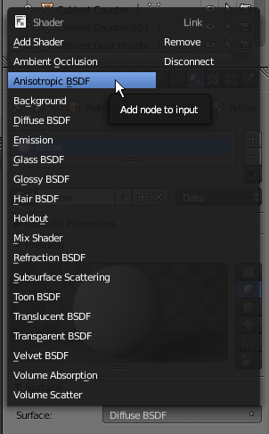
- In the Properties window, on the right side of Surface, click Diffuse BSDF
- In the menu that appears, click Anisotropic BSDF:
- In the Outliner, click Regular Pot to select it
- In the Material tab of the Properties window, click the New button
- In the Surface section, click Diffuse BSDF and click Anisotropic BSDF
- In the Outliner, click Stainless Steel Pot to select it
- On the menu bar of the Node Editor, click the New button
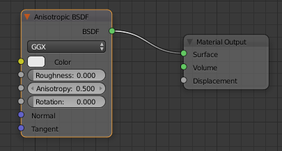
- In the Material section of the Properties window, click Diffuse BSDF and click Anisotropic BSDF
- In the Outliner, click Small Pot to select it
- On the menu bar of the Node Editor, click the New button
- In the Material section of the Properties window, click Diffuse BSDF and click Anisotropic BSDF
- In the Outliner, click Egg Skillet to select it
- On the menu bar of the Node Editor, click the New button
- In the Node Editor, right-click anywhere inside the Diffuse BSDF window to give it focus
- Press Delete to remove the window
- Position the mouse in the Node Editor. Press Shift + A -> Shader -> Anisotropic BSDF
- Position the mouse on the left side of the Material Output window and click
- Drag the green BSDF button and drop it on the green Surface button
- In the Outliner, click Heat Skillet to select it it
- On the menu bar of the Node Editor, click the New button
- On the menu bar of the Node Editor, click Add -> Shader -> Anisotropic BSDF
- Position the window below, or on the left of, the Diffuse BSDF window
- Drag the green BSDF button from the Anisotrpic BSDF window and drop on Surface of Material Output
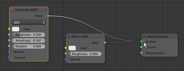
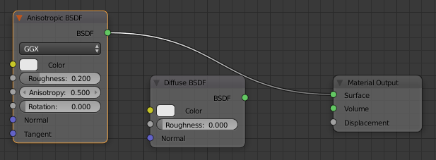
- Click anywhere inside the Diffuse BSDF window to select it
- Press Delete
- In the Outliner, click Refrigerator Top Door Handle to select it
- In the Material tab of the Properties window, click the New button
- Still in the Material tab of the Properties window, click Material.005 to select the name
- Type Silver Grabber and press Enter
- In the Material tab of the Properties window, click Diffuse BSDF and click Anisotropic BSDF
- In the Outliner, click Cabinet Door Handle - Vertical Left to select it
- On the menu bar of the Node Editor, click the New button
- On the menu bar of the Node Editor, click Material.005 to select the name
- Type Gray Story and press Enter
- In the Material tab of the Properties window, click Diffuse BSDF and click Anisotropic BSDF
- In the Outliner, click Oven Door Handle - Top to select it
- In the Material tab of the Properties window, click the New button
- Still in the Material tab of the Properties window, click Diffuse BSDF and click Anisotropic BSDF
- In the Outliner, click Stove Knob to select it
- On the menu bar of the Node Editor, click the New button
- In the Material tab of the Properties window, click Diffuse BSDF and click Anisotropic BSDF
- On the top menu, click Render -> Render Image to preview the result. Here is an example:

- On the menu bar of the UV/Image Editor, click Image -> Save As Image
- Set the name as Kitchen2 and click Save As Image
- After saving the file, press Esc to close the render view
The Color of an Anisotropic Object
, Blender.
 Practical Learning: Painting an Anisotropic Object
- In the Outliner, click Stainless Steel Pot to select it
- In the Material section of the Properties window, click the white side of the Color button
- Click inside the righr vertical bar to select a gray color (alternatively, set the RGB value as R = .785, G = .785, and B = .785)
- In the Outliner, click Egg Skillet to select it
- In the Node Editor, click the Color button
- Set the RGB values as follows:
R: .815
G: .815
B: .855
- In the Outliner, click Refrigerator Top Door to select it
- In the Material section of the Properties window, click the dark-gray button on the extreme right side of the Color button
- In the menu that appears, click RGB
- Click the horizontal bar below the color wheel
- Set the RGB values as follows:
R: .825
G: .625
B: .325
- In the Outliner, click Regular Pot
- On the menu bar of the Node Editor, click Add -> Input -> RGB
- Position the mouse on the left side of the Anisotropic BSDF window and click
- Drag the yellow button from the RGB window and drop it on the yellow button of the Anisotropic BSDF window
- Click the horizontal button below the color wheel
- Set the RGB values as follows:
R: .265
G: .015
B: .005
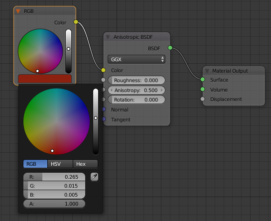
- Press F12 preview the rendering. Here is an example:

- On the toolbar of the UV/Image Editor, click Image and click Save As Image
- Set the file name as Kitchen3 and click Save As Image
- After saving the result, press Esc to return to the model
The Roughness of a Glass
Like the Diffuse material, the Glass BSDF has a characteristic named Roughness. The Roughness of a glass is a decimal value between 0.0 and 1.00. When the value is set to 0 (or 0.00), the object is perfectly transparent. In this case, depending on the type of object, you may be able to see what is on the other side of the object. If/When the roughness is set to 1 (or 1.00), the transparency level of the object is semi-completely blurred.An object is referred to as glossy if it shines. To support this, Blender provides a material named Glossy BSDF.
 Practical Learning: Applying Roughness to an Anisotropic Object
- In the Outliner, click Stainless Steel Pot to select it
- In the Material tab of the Properties Editor, Click the Roughness value to select it
- Type .325 and press Enter
- In the Outliner, click Refrigerator Top Door (alternatively, in the work area, right-click one of the doors of the refrigerator) to select it
- In the Node Editor, click the Roughness value to select it
- Type .275 and press Enter
- In the Outliner, click Refrigerator Top Door Handle to select it
- On the toolbar of the Node Editor, click Add -> Input -> Value
- Click on the left side of the Anisotropic BSDF window
- In the Value window, click the value to select it
- Type .175 and press Enter
- Drag the gray button from Value to the gray button of Roughness
- In the Outliner, click Small Pot
- In the Material tab of the Properties window, click the dark-gray button on the right side of Roughness
- In the menu that appears, click Value
- In the Material section of the Properties window, below the Value button, click the value to select it
- Type .225 and press Enter
- In the Outliner, click Regular Pot to select it
- On the menu bar of the Node Editor, click Add -> Input -> Value
- Position the mouse on the left side of the Anisotropic BSDF window and below the RGB window, then click
- In the Value window, click the value to select it
- Type .105 and press Enter
- Drag the button from the Value window to the Roughness button
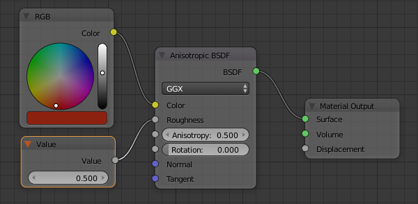
- In the Outliner, click Egg Skillet to select it
- Position the mouse in the Node Editor. Press Shift + A -> Input -> Value
- Position the mouse on the left side of the Anisotropic BSDF window and click
- Draw a line between the Value button of the Value window and the Roughness button of the Anisotropic BSDF window
- In the Value window, click the value to select it
- Type .625 and press Enter
- In the Outliner, click Oven Door Handle - Top to select it
- In the Material tab of the Properties window, click the Roughness value to select it
- Type .025 and press Enter
- In the Outliner, click Cabinet Door Handle - Vertical Left to select it
- In the Node Editor, click set the Roughness value to .115
- Press F12 preview the rendering. Here is an example:

- On the toolbar of the UV/Image Editor, click Image and click Save As Image
- Set the file name as Kitchen4 and click Save
- After saving the file, press Esc
 Practical Learning: Completing the Scene
- In the Outliner, click Refrigerator Body to select it
- In the Properties window, click Use Nodes
- In the Properties window, click the dark-gray button on the right side of Color and click RGB
- In the Node Editor, click the horizontal bar below the color wheel
- Set the RGB values as follows:
R: .825
G: .625
B: .325
- In the work area, right-click any cabinet door
- In the Material section of the Properties window, click the New button
- On the menu bar of the Node Editor, click Material.008 to select the name
- Type Rose Wood and press Enter
- In the Properties window, click the dark-gray button on the extreme right side of Color and click RGB
- Click the horizontal bar below the color wheel and click Hex
- Click the color value to select it
- Type E7B06F and press Enter
- In the Outliner, click Stove Ventilator to select it
- On the menu bar of the Node Editor, click the New button
- In the Material section of the Properties window, click the dark-gray button on the extreme sight side of the Color button and select RGB
- Click the horizontal bar below the color wheel and click RGB
- Set the color value as
R: .145
G: .145
B: .145
- In the Outliner, click Kitchen Counter - Left to select it
- On the menu bar of the Node Editor, click the New button
- In the Material section of the Properties window, click Diffuse BSDF and click Glass BSDF
- In the Material section of the Properties window, click the dark-gray button on the extreme sight side of the Color button and select RGB
- In the Node Editor, click the horizontal bar below the color wheel
- Set the RGB value as follows:
R: .865
G: .865
B: .865
- In the Properties window, click the dark-gray button on the extreme right side of Roughness and click Value
- In the Node Editor, click the Roughness value to select it
- Type .125 and press Enter
- In the Outliner, click Utensils Holder to select it
- On the menu bar of the Node Editor, click the New button
- In the Materials section of the Properties window, click the dark-gray button on the extreme right side of Color and select RGB
- Click the vertical bar below the color wheel and click RGB
- Set the color value as:
R: .055
G: .155
B: .5
- In the Outliner, click Pot Support to select it
- In the Materials section of the Properties window, click the New button
- In the Node Editor, click the Color button and click HSV
- Set the values as follows:
H: 0
S: 0
V: .275
- In the Outliner, click Stove Top to select it
- On the menu bar of the Node Editor, click the New button
- On the menu bar of the Node Editor, click Material.012 to select the name
- Type Brown Thang and press Enter
- In the Node Editor, click Diffuse BSDF to select its window
- Press X to remove that window
- Position the mouse in the Node Editor.
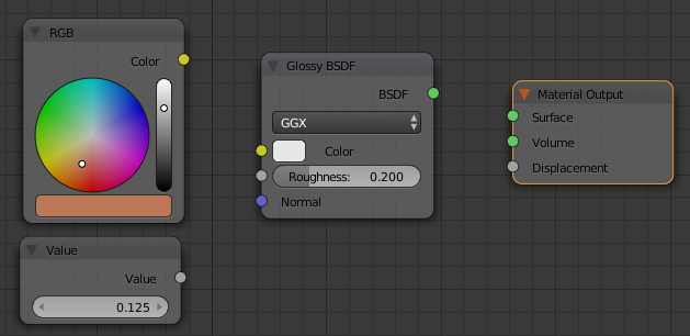
Press Shift + A -> Shader -> Glossy BSDF
- Click on the left side of the Material Output window
- On the toolbar of the Node Editor, click Add -> Input -> RGB
- Click on the left side of the Glossy BSDF window
- Click the horizontal bar below the color wheel and click RGB
- Set the color as:
R: .5
G: .185
B: .095
- Position the mouse in the work area.
Press Shift + A -> Input -> Value
- Click below the RGB window
- In the Value window, click the value to select it
- Type .125 and press Enter
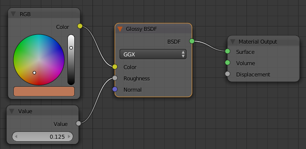
- Draw a line from the yellow circle of the RGB window to the yellow Color button of the Glossy BSDF window
- Draw a line from the gray circle of Value to the gray circle of Roughness
- Draw a line from the green BSDF button to the green Surface:
- In the Outliner, click Stove Oven to select it
- On the menu bar of the Node Editor, click the button on the left side of New and click Brown Thang
- In the Outliner, click Oven Glass to select it
- On the menu bar of the Node Editor, click the New button
- In the Material section of the Properties window, click Diffuse BSDF and click Glass BSDF
- In the Material section of the Properties window, click the dark-gray button on the extreme right side of Color and click RGB
- In the Node Editor, click inside the color wheel to select a light-blue color (or click the horizontal bar below the color wheel and set the color to R = .645, G = .685, and B = .815)
- In the Properties window, click the dark-gray button on the extreme right side of Roughness and click Value
- In the Value window of the Node Editor, click the value to select it
- Type .725 and press Enter
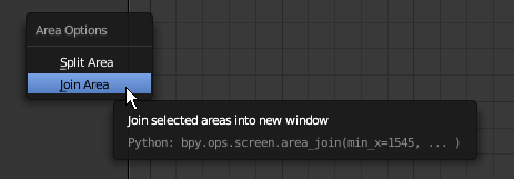
- Right-click the lower border of the Node Editor and click Join Area
- Click inside the Node Editor
- In the menu that appears, click Join Area:
- In the Outliner, click Left Wall to select it
- In the Material section of the Properties window, click the New button
- In the Properties window, click Material.013 to select the name
- Type Cream and press Enter
- Click the white Color button and click Hex
- Set the color value as FFF8DC
- In the Outliner, click Back Wall to select it
- In the Properties window, click the button on the left side of New and click Cream
- In the Outliner, click Floor to select it
- In the Material section of the Properties window, click the New button
- Click the white Color button and click Hex
- Set the color value as D2D2D2
- In the Properties window, click the Render button. Here is an example:

- On the toolbar of the UV/Image Editor, click Image and click Save As Image
- Set the file name as Kitchen5 and click Save
- After saving the file, press Esc


![]() Practical Learning: Starting the Project
Practical Learning: Starting the Project![]() Practical Learning: Starting a Refrigerator
Practical Learning: Starting a Refrigerator
![]() Practical Learning: Modeling a Refrigerator Door
Practical Learning: Modeling a Refrigerator Door


![]() Practical Learning: Creating the Main Door of the Refrigerator
Practical Learning: Creating the Main Door of the Refrigerator
![]() Practical Learning: Creating Door Handles
Practical Learning: Creating Door Handles


![]() Practical Learning: Creating a Kitchen Cabinet - Bottom-Left
Practical Learning: Creating a Kitchen Cabinet - Bottom-Left![]() Practical Learning: Modeling a Cabinet Drawer - Left
Practical Learning: Modeling a Cabinet Drawer - Left![]() Practical Learning: Modeling a Top Cabinet - Left
Practical Learning: Modeling a Top Cabinet - Left![]() Practical Learning: Modeling a Cabinet Door - Top-Left
Practical Learning: Modeling a Cabinet Door - Top-Left![]() Practical Learning: Modeling a Kitchen Counter - Left
Practical Learning: Modeling a Kitchen Counter - Left


![]() Practical Learning: Modeling a Cabinet Handle
Practical Learning: Modeling a Cabinet Handle
![]() Practical Learning: Creating a Cabinet Handle - Horizontal Bottom-Left
Practical Learning: Creating a Cabinet Handle - Horizontal Bottom-Left![]() Practical Learning: Creating a Cabinet Handle - Vertical Bottom-Left
Practical Learning: Creating a Cabinet Handle - Vertical Bottom-Left![]() Practical Learning: Modeling a Kitchen Stove
Practical Learning: Modeling a Kitchen Stove


![]() Practical Learning: Modeling the Glass of a Stove
Practical Learning: Modeling the Glass of a Stove
![]() Practical Learning: Creating the Top Oven Handle
Practical Learning: Creating the Top Oven Handle![]() Practical Learning: Creating the Bottom Oven Handle
Practical Learning: Creating the Bottom Oven Handle![]() Practical Learning: Modeling the Top of the Stove
Practical Learning: Modeling the Top of the Stove


![]() Practical Learning: Creating Stove Knobs
Practical Learning: Creating Stove Knobs![]() Practical Learning: Creating Pots Support
Practical Learning: Creating Pots Support




![]() Practical Learning: Creating a Kitchen Stove Ventilator
Practical Learning: Creating a Kitchen Stove Ventilator![]() Practical Learning: Extending the Kitchen Cabinets
Practical Learning: Extending the Kitchen Cabinets![]() Practical Learning: Modeling a Utensils Holder
Practical Learning: Modeling a Utensils Holder


![]() Practical Learning: Modeling a Steel Pot
Practical Learning: Modeling a Steel Pot


![]() Practical Learning: Modeling another Pot
Practical Learning: Modeling another Pot![]() Practical Learning: Modeling One More Pot
Practical Learning: Modeling One More Pot![]() Practical Learning: Creating a Skillet
Practical Learning: Creating a Skillet![]() Practical Learning: Creating another Skillet
Practical Learning: Creating another Skillet![]() Practical Learning: Creating a Kitchen
Practical Learning: Creating a Kitchen![]() Practical Learning: Applying Introductory Materials
Practical Learning: Applying Introductory Materials
![]() Practical Learning: Applying an Anisotropic Material
Practical Learning: Applying an Anisotropic Material


![]() Practical Learning: Painting an Anisotropic Object
Practical Learning: Painting an Anisotropic Object
![]() Practical Learning: Applying Roughness to an Anisotropic Object
Practical Learning: Applying Roughness to an Anisotropic Object
![]() Practical Learning: Completing the Scene
Practical Learning: Completing the Scene

