 |
Blender Materials: Mixing Some Materials |
|
Introduction
Many of the materials used in Blender are complete by themselves. One way to enhance the effects of materials is to combine them. This operation includes the materials we have already seen: Diffusion BSDF, Glossy BSDF, and Glass BSDF. Blender provides many options to that effect.
 Practical Learning: Starting the Project
- Start Blender
- In the Properties window, click the Object button

- Position the mouse on the default cube and press X
- In the menu that appears, click Delete
- In the Outliner, click the Restrict Viewport Visibility button (the eye) on the right side of Lamp to hide it
- In the Outliner, click the Restrict Rendering button (the camera) on the right side of Lamp to hide it
 Practical Learning: Creating a Classic Cup
- On the Tools window, click Create
- Click Cylinder
- In the Object tab of the Properties window, click Cylinder to select the name
- Type Classic Cup and press Enter
- In the Transform section, change the following values:
Location - X: 1.275
		     Y: -1.55
		     Z: 3.75
Scale    - X: .35
		     Y: .35
           Z: .55
- On the menu bar of the 3D-View, click Object Mode and click Edit Mode
- On the menu bar of the 3D-View, click the Face Select button

- Right-click the top face of the cylinder to select it
- Press S to resize
- Type 1.25 and press Enter:
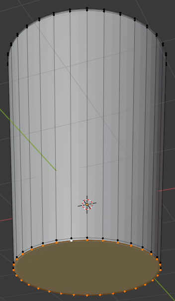
- Position the mouse on the cylinder and press X to delete
- In the menu that appears, click Faces:
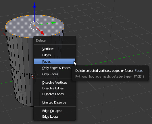
- On the menu bar of the 3D-View, click the Vertex Select button

- Press and hold Alt
- Right-click one of the top vertices to select all of them
- Release Alt:
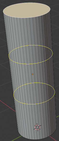
- Press E as if you want to extrude and press Enter
- Press S as if you want to resize
- Type .95 and press Enter:
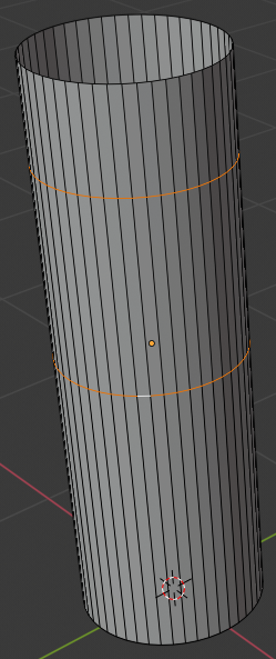
- Press Z to display in wireframe
- In the Numeric Pad, press 1 to display the front view
- Press 5 to work in an orthogonal view
- Press E and press Enter
- Press G
- Press Z
- Type -1.05 and press Enter:
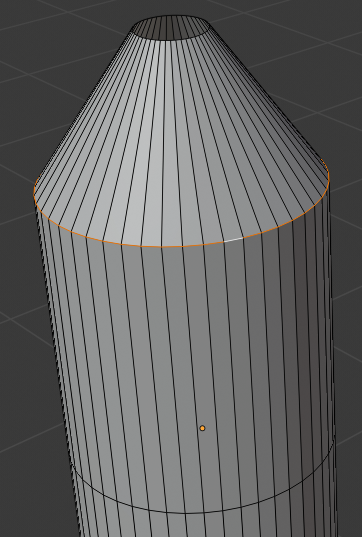
- Press S
- Type .75 and press Enter:
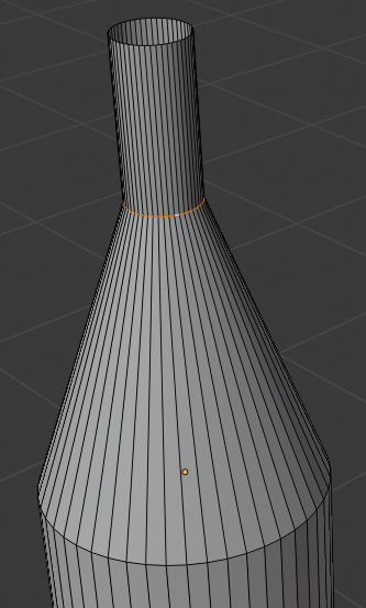
- Press Z to display in Solid view
- Press Tab to display in Object Mode
- Move the view to display the cup in perspective:
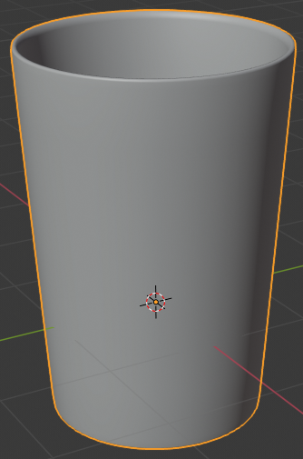
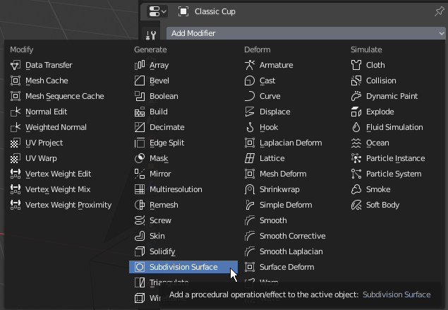
- In the Properties window, click the Modifiers button

- Click Add Modifier and click Subdivision Surface:
- Set the View value to 2
- Position the mouse on the cylnder and press Tab to display in Edit Mode
- Press Ctrl + R and get a horizontal ellipse on the cylinder
- Click to create a cut
- Move the cut as close as possible to the top border:
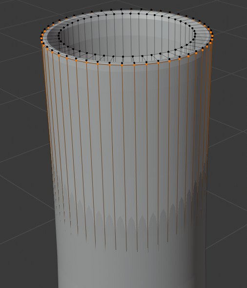
- Press Ctrl + R and get a horizontal ellipse on the cylinder
- Click to create a cut
- Move the cut as close as possible to the top border:
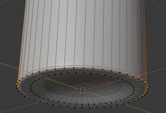
- Position the mouse inside the top border. Press Ctrl + R to get a horizontal inside cut
- Click to create a cut
- Move the inside cut as close as possible to the top border:
- Press Z to display in wireframe
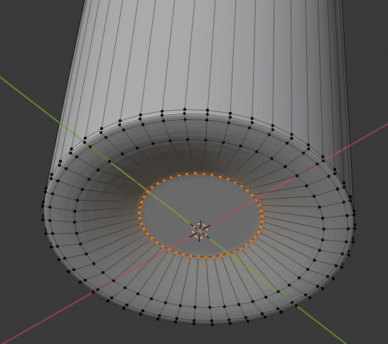
- Psition the mouse inside the top border. Press Ctrl + R to get a horizontal inside cut
- Click once to create the cut
- Move the inside cut as close as possible to the inside bottom border:
- Press Z to exit the wireframe
- Move the view so you can see the bottom side of the cylinder
- Press and hold Alt
- Right-click one of the bottom vertices to select them
- Release Alt:
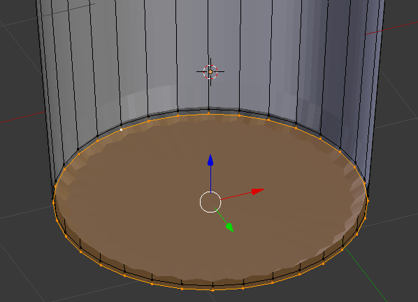
- Press E and press Enter
- Press S
- Type .95 and press Enter:
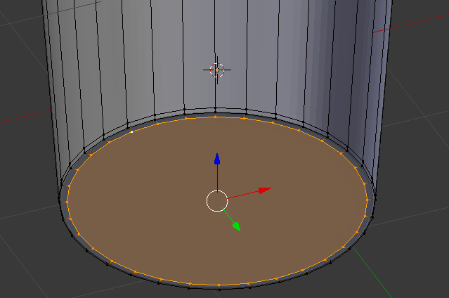
- Press Tab to display in Object Mode
- In the Properties window, click Apply
- In the Tools window and in the Tools tab, click Smooth:
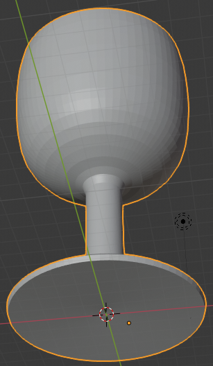
- In the Outliner, click the Restricted Viewport Visibility button (the eye) on the right side of Classic Cup to hide it from the work area
- In the Outliner, click the Restricted Rendering button (the camera) on the right side of Classic Cup
 Practical Learning: Creating a Bottle of Red Wine
- In the Tools window, click Create
- Click Cylinder
- In the Add Cylinder section below the Tools window, change the following value:
Vertices: 48
- In the Properties window, click the Object button

- In the Object tab of the Properties window, click Cylinder to select it
- Type Bottle of Red Wine and press Enter
- In the Object tab of the Properties window, change the following values:
Location - X: 4.02
		     Y: 1.55
           Z: 4.455
Scale    - X: .4
		     Y: .4
           Z: 1.25
- To prepare to edit the cylinder, on the menu bar of the 3D View, click Object Mode and click Edit Mode
- Move the view and zoom in so you can see the top side of the cylinder
- On the menu bar of the 3D-View, click the Face Select button

- On the cylinder, right-click the top face of the cylinder:
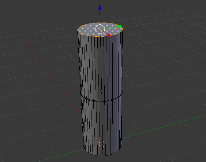
- Press X to delete
- On the menu that appears, click Faces
- Position the mouse on the cylinder, press Ctrl + R and make sure you see a horizontal ellipse or line
- Click twice to confirm the cut
- Press G to move the cut
- Press Z to move it vertically
- Type .775 and press Enter:
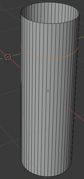
- Position the mouse above the bottom border of the cylinder, press Ctrl + R and make sure you see a horizontal ellipse or line
- Click twice to confirm the cut:
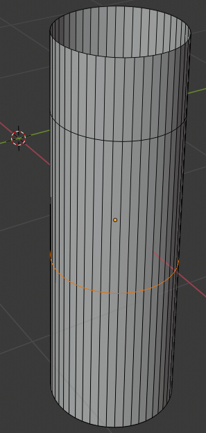
- Press G to move the cut
- Press Z to move vertically
- Type .55 and press Enter:
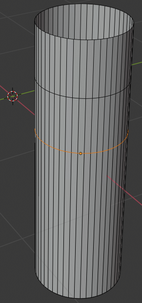
- On the menu bar of the 3D-View, click the Vertex Select button

- Press and hold Alt
- Right-click one of the vertices on the top side of the cylinder to select all top vertices of the bottle
- Release Alt:
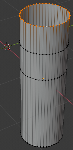
- Press S to resize
- Type .25 and press Enter
- Press and hold Alt
- Right-click the second line from the top of the cylinder to select the horizoontal cut
- Release Alt:
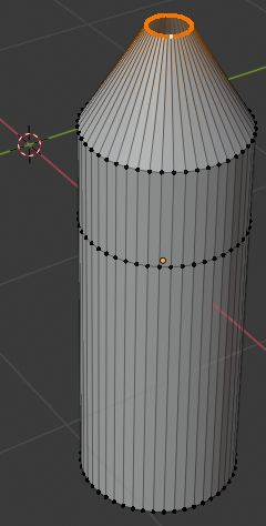
- Press S to resize
- Type .25 and press Enter:
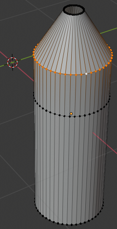
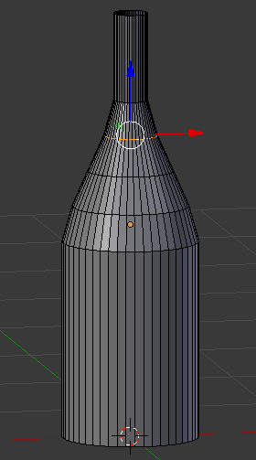
- The second and third horizontal lines are the neck of the bottle.
Position the mouse on the neck of the bottle, press Ctrl + R and make sure you see a horizontal ellipse or line
- Click twice to confirm the cut:
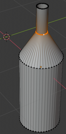
- Press S to resize
- Type 1.35 and press Enter:
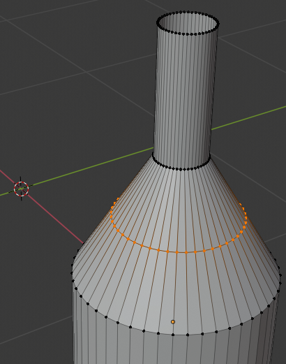
- Position the mouse between the third line from the top of the bottle and the fourth line, press Ctrl + R and make sure you see a horizontal ellipse or line
- Click twice to confirm the cut
- Press S to resize
- Type 1.075 and press Enter:
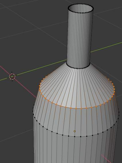
- Position the mouse between the second line from the top of the bottle and the third line, press Ctrl + R and make sure you see a horizontal ellipse or line
- Click twice to confirm the cut
- Press S to resize
- Type .855 and press Enter:
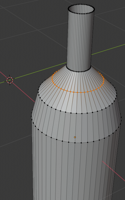
- Position the mouse between the second line from the top of the bottle and the third line, press Ctrl + R and make sure you see a horizontal ellipse or line
- Click twice to confirm the cut
- Press S to resize
- Type 1.05 and press Enter:
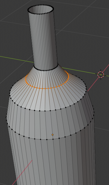
- Position the mouse between the third line from top and the fourth line from top, press Ctrl + R and make sure you see a horizontal ellipse or line
- Click twice to confirm the cut
- Press S
- Type 855 and press Enter:
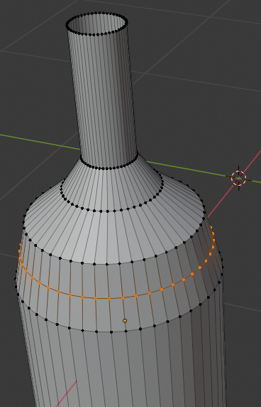
- Move the view so you can see the bottom side of the cylinder
- On the menu bar of the 3D-View, click the Vertex Select button

- Press and hold Alt
- Right-click one of the vertices on the bottom side of the cylinder to select all bottom vertices of the bottle
- Release Alt:
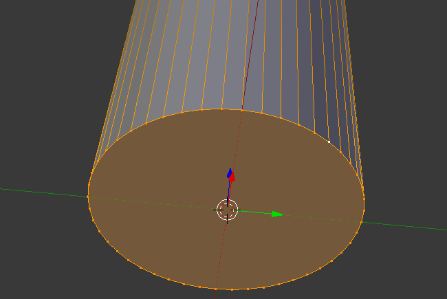
- Press E as if you want to extrude
- Press S to move the vertices
- Type .85 and press Enter:
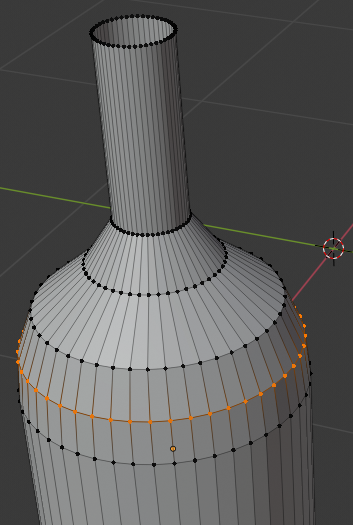
- Press E
- Press S
- Type 0 and press Enter:
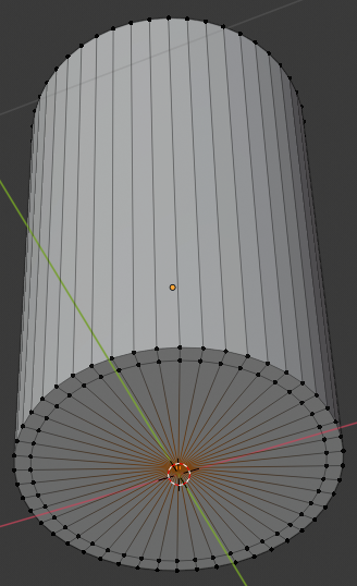
- On the cylinder, the central-bottom vertex should be selected (otherwise select it)
In the Numeric Pad, press 1 to get the front orthogonal view
- Press Z to display the object as a wireframe
- Press G to prepare to move the vertex
- Press Z to move vertically
- Type .25 and press Enter:
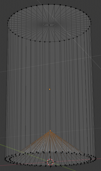
- Press Z to exit from wireframe
- Press Tab to display in Object Mode
- In the Object tab of the Properties window, click the Modifiers button
- Click Add Modifier and click Solidify:
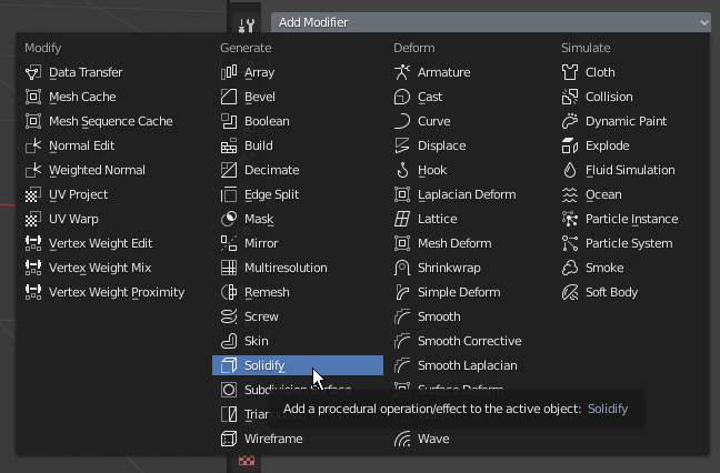
- Click the Thickness value, type .02 and press Enter
- Click Apply
- Click Add Modifier and click Subdivision Surface
- Set the View value to 2
- Position the mouse on the bottle and press Tab to display in Edit Mode
- Position the mouse in the upper section of the bottle, press Ctrl + R to get a horizontal line
- Click once to accept the line
- Move the line up as close as possible to the top border:
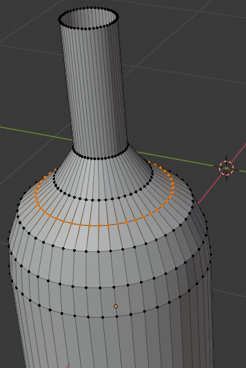
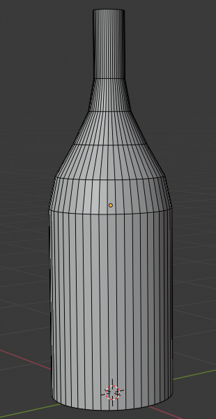
- Position the mouse inside the top opening of the bottle, press Ctrl + R to get a horizontal line
- Click once to confirm
- Move the cut up as close as possible to the top border:
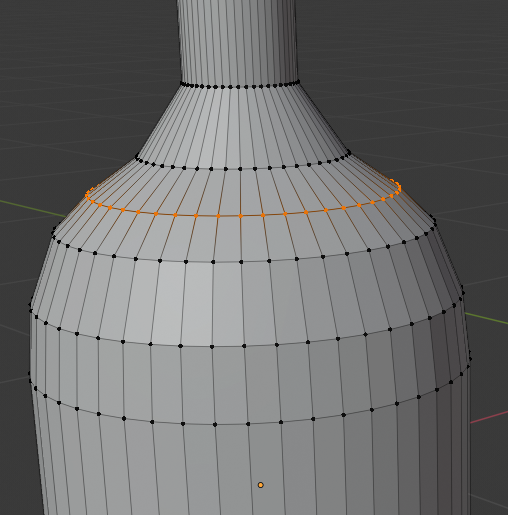
- Move the shape so you can see the lower part of the bottle
- Press Ctrl + R to get a horizontal cut and click once to cut
- Move the line down close to the bottom border:
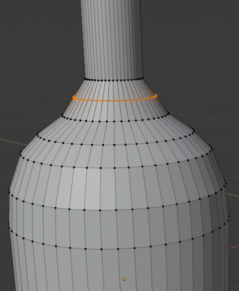
- On the menu bar of the 3D View, click Edit Mode and click Object Mode
- In the Properties window, click Apply
- In the Tools window, click the Tools tab and click Smooth:
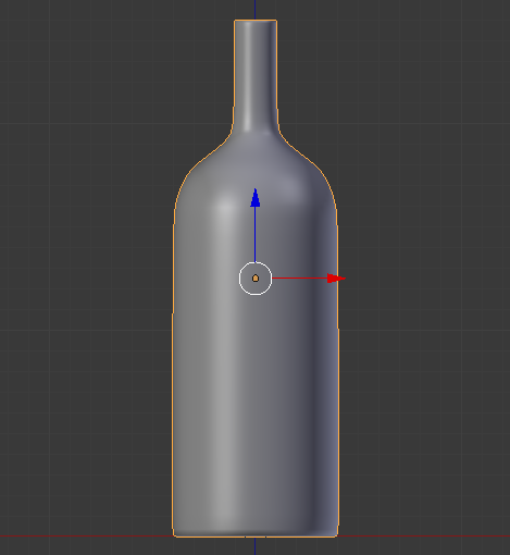
- In the Outliner, click the Restricted Viewport Visibility button (the eye) on the right side of Bottle of Red Wine to hide it from the scene
- In the Outliner, click the Restricted Rendering button (the camera) on the right side of Bottle of Red Wine
 Practical Learning: Modeling Red Wine
- In the Create tab of the Tools window, click Cylinder
- In the Object tab of the Properties window, change the following values:
Name:      Red Wine
Location - X: 4.02
		     Y: 1.55
           Z: 4.235
Scale	   - X: .365
		     Y: .365
- On the menu bar of the 3D View, click Object Mode and click Edit Mode
- Position the mouse on the cylinder, press Ctrl + R and make sure you see a horizontal ellipse or line
- Click twice to confirm the cut
- Press G to move the cut
- Press Z to move it vertically
- Type .5 and press Enter:

- Position the mouse below the top border, press Ctrl + R and make sure you see a horizontal ellipse or line
- Click twice to confirm the cut
- Press G to move the cut
- Press Z to move vertically
- Type -.125 and press Enter
- Press S to resize
- Type .975 and press Enter:
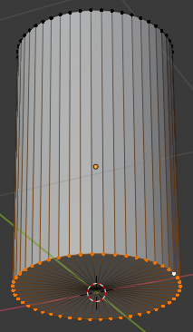
- Position the mouse below the top border, press Ctrl + R and make sure you see a horizontal ellipse or line
- Click twice to confirm the cut
- Press G to move the cut
- Press Z to move vertically
- Type -.1 and press Enter
- Press S to resize
- Type .875 and press Enter:
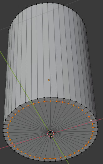
- Position the mouse below the top border, press Ctrl + R and make sure you see a horizontal ellipse or line
- Click twice to confirm the cut
- Press G to move the cut
- Press Z to move vertically
- Type -.05 and press Enter
- Press S to resize
- Type .465 and press Enter:
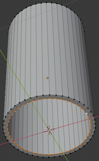
- Position the mouse below the top border, press Ctrl + R and make sure you see a horizontal ellipse or line
- Click twice to confirm the cut
- Press S to resize
- Type .4 and press Enter:
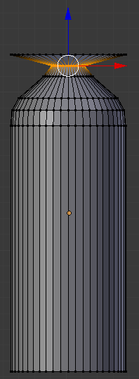
- On the menu bar of the 3D-View, click the Vertex Select button

- Press and hold Alt
- Right-click one of the vertices on the top side of the cylinder to select all top vertices of the bottle
- Release Alt:
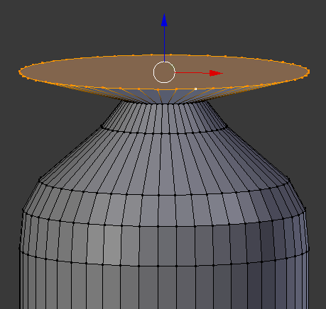
- Press S to resize
- Type .25 and press Enter
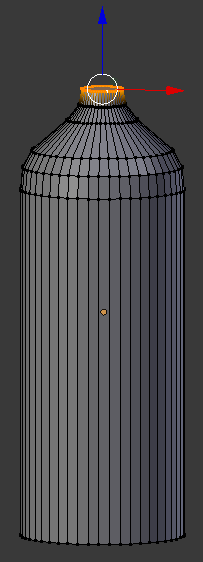
- On the menu bar of the 3D View, click Edit Mode and click Object Mode
- In the Tools window, click the Tools tab and click the Smooth button
- In the Outliner, click the Restricted Viewport Visibility button on the right side of Red Wine to hide it
- In the Outliner, click the Restricted Rendering button (the camera) on the right side of Red Wine
 Practical Learning: Creating an Empty Bottle
- In the Outliner, click the Restricted Viewport Visibility button (the eye) on the right side of Bottle of Red Wine to display it
- In the work area, right-click the bottle to select it
- Press Shift + D to make a copy of the bottle and press Enter
- In the Properties window, click Bottle of Red Window.001 to select it
- Type Chantilly and press Enter
- In the Object tab of the Properties window, change the following value:
Location - X: 0
- In the Outliner, click the Restricted Viewport Visibility button on the right side of Chantilly to hide it
- In the Outliner, click the Restricted Rendering button (the camera) on the right side of Chantilly
 Practical Learning: Modeling a Bottle Cap
- On the menu bar of the 3D View, click Add -> Mesh -> Cylinder
- In the Add Cylinder section below the Tools window, change the following value:
Vertices: 32
- In the Object tab of the Properties window, change the following values:
Name:      Bottle Cap
Location - X: 4.00945
		     Y: 1.55
           Z: 5.575
Scale    - X: .108
		     Y: .108
           Z: .15
- Position the mouse in the work area and press Tab to display the cap (or cork) in Edit Mode
- Press Ctrl + R and create a horizontal cut on the shape, then move it up as follows:
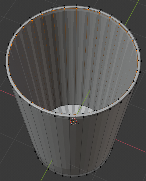
- Create another horizontal cut and position it as follows:
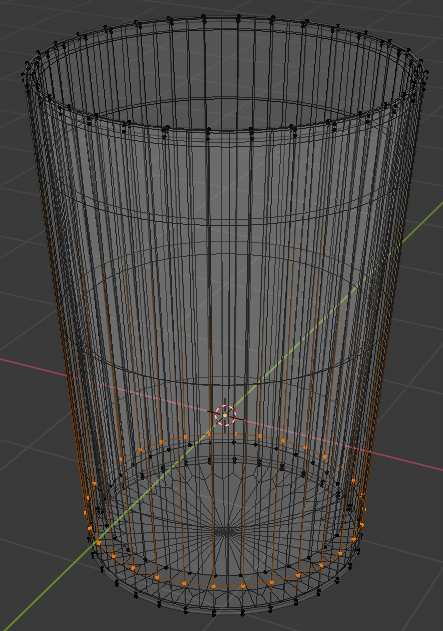
- On the menu bar of the 3D-View, click the Face Select button

- Press and hold Shift, then right-click one of the middle faces, and release Shift:
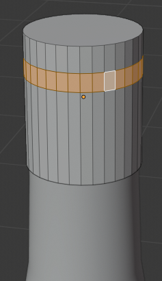
- Press E to extrude
- Press S to move the faces
- Type 1.1 and press Enter:
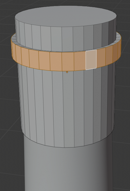
- Press Tab to display the cap (or cork) in Object Mode
- In the Outliner, click the Restricted Viewport Visibility button (the eye) on the right side of Bottle Cap to hide it
- In the Outliner, click the Restricted Rendering button (the camera) on the right side of Bottle Cap
 Practical Learning: Creating a Bottle of White Wine
- In the Tools window, click Create
- Click Cylinder
- In the Add Cylinder section below the Tools window, change the following value:
Vertices: 48
- In the Object tab of the Properties window, change the following values:
Name:      Bottle of White Wine
Location - X: 2
		     Y: 1.55
           Z: 4.455
Scale    - X: .4
		     Y: .4
           Z: 1.25
- Position the mouse in the work area and press Tab to display in Edit Mode
- Move the view so you can see the top side of the cylinder
- Press Ctrl + Tab and, on the menu that appears, click Face
- On the cylinder, right-click the top face of the cylinder
- Press X
- Click Faces
- Press Ctrl + R and make sure you get a horizontal cut on the object
- Roll the middle mouse button slightly up to get 2 cuts:
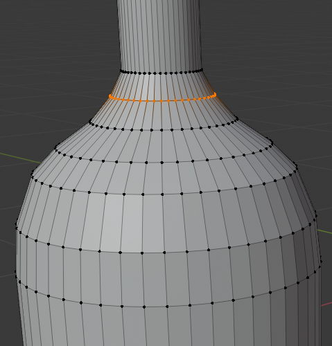
- Then click once to accept the cuts
- Press G to move the cuts
- Press Z to move them vertically
- Type .45 and press Enter. Here is an example:
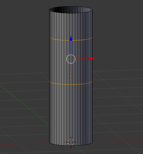
- Press and hold Alt
- Right-click a vertext in the top border to select all of them
- Release Alt
- Press S to resize
- Type .25 and press Enter
- Press and hold Alt
- Right-click a vertex in the second cut to select those vertices
- Release Alt
- Press S to resize
- Type .25 and press Enter:
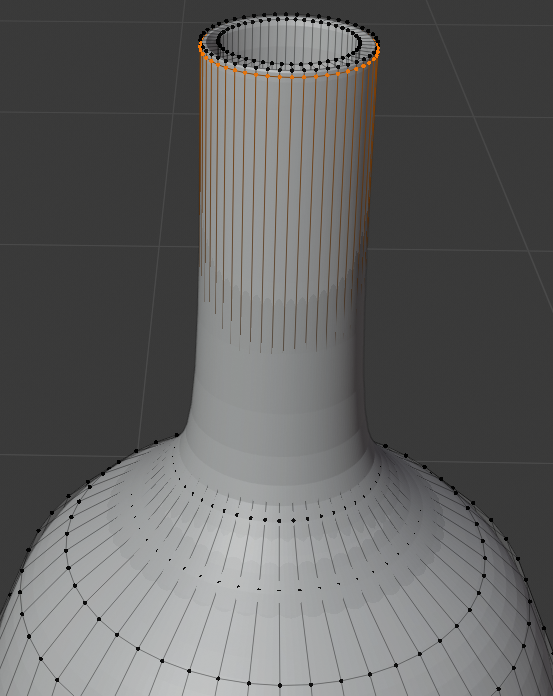
- Position the mouse in the middle part of the bottle and press Ctrl + R to get a horizontal cut
- Roll the middle mouse button to get 3 cut, then click twice to confirm. Here is an example:
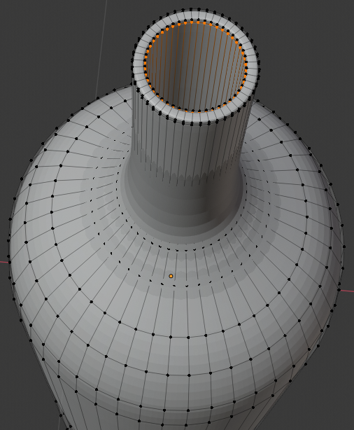
- Press and hold Alt, then right-click a cut to select its vertices, then release Alt, then press S and move the mouse to resize the cut. Model the bottle as follows:
- Move the view so you can see the bottom side of the bottle
- Press Alt
- Right-click a bottom vertext to select the whole border
- Then release Alt:
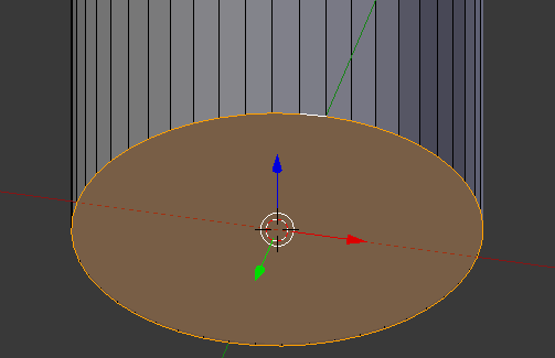
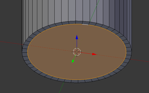
- Press E and press Enter
- Press S
- Type .9 and press Enter:
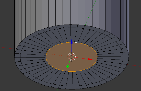
- Press E and press Enter
- Press S
- Type .5 and press Enter:
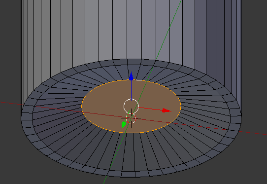
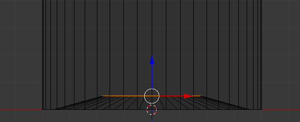
- Press G to prepare to move the vertex
- Press Z to move vertically
- Type .1 and press Enter:
- Press Tab to display the Object Mode
- In the Properties window, click the Modifiers button
- Click Add Modifier and click Solidify:

- Click the Thickness value, type.02 and press Enter
- Click Apply
- Click Add Modifier and click Subdivision Surface
- Set the View value to 2
- Position the mouse on the bottle and press Tab to display in Edit Mode
- Position the mouse in the upper section of the bottle, press Ctrl + R to get a horizontal line
- Click twice to confirm
- Move the blue line (Z axis) up as close as possible to the top border:

- Move the view so you can see the bottom part of the bottle
- Press Ctrl + R to get a horizontal cut and press twice to confirm
- Move the line down close to the bottom border:
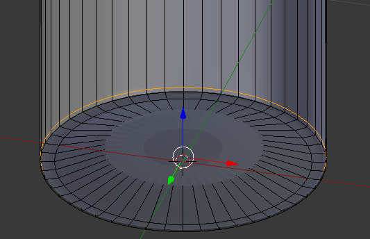
- On the menu bar of the 3D View, click Edit Mode and click Object Mode
- In the Properties window, click Apply
- In the Tools window, click the Tools tab and click Smooth:
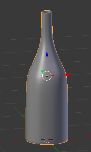
- In the Outliner, click the Restricted Viewport Visibility button on the right side of Bottle of White Wine to hide it
- In the Outliner, click the Restricted Rendering button on the right side of Bottle of White Wine to hide it
 Practical Learning: Creating the White Wine
- In the Properties window, click the Object button

- On the menu bar of the 3D View, click Add -> Mesh -> Cylinder
- In the Add Cylinder section below the Tools window, change the following value:
Cap Fill Type: Triangle Fan
- In the Object tab of the Propertles window, change the following values:
Name:      White Wine
Location - X: 2
		     Y: 1.55
           Z: 3.75
Scale    - X: .365
           Y: .365
           Z: .5
- On the menu bar of the 3D View, click Object Mode and click Edit Mode
- On the menu bar of the 3D-View, click the Vertex Select button

- Right-click the top-middle vertex to select it
- Press X to delete it
- In the menu that appears, click Vertices:
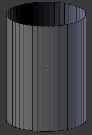
- Press and hold Alt
- Right-click one of the vertices on the top border of the cylinder to select all top vertices of the cylinder
- Release Alt:
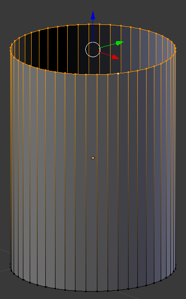
- Press E to extrude and press Enter
- Press S to resize the new face
- Type .85 and press Enter:
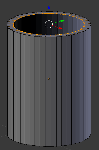
- Press G to move the vertices
- Press Z to move them vertically
- Type -.02 and press Enter:
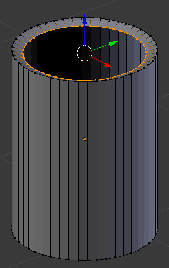
- Press E to extrude and press Enter
- Press S to resize
- Type 0 and press Enter to close the face:
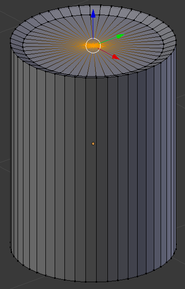
- Move the view so you can see the bottom side of the cylinder
- Press and hold Alt
- Right-click one of the vertices on the bottom side of the cylinder to select all bottom vertices of the cylinder
- Release Alt:
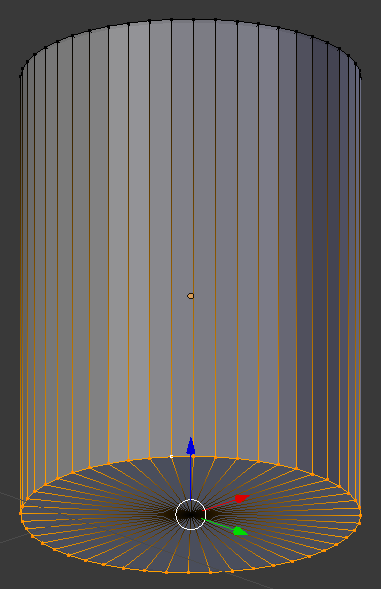
- Press E
- Press S
- Type .9 and press Enter:
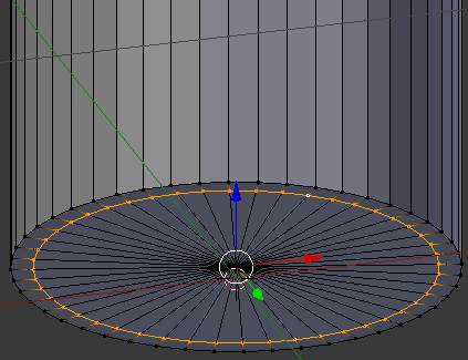
- Right-click the middle vertex to select it:
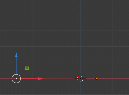
- Press Z to display in wireframe
- On the cylinder, the central-bottom vertex should be selected (otherwise select it)
Press G to prepare to move the vertex
- Press Z to move vertically
- Type .24 and press Enter:
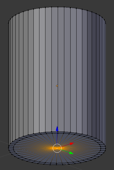
- On the menu bar of the 3D View, click Edit Mode and click Object Mode
- In the Tools window, click the Tools tab
- Click Smooth
- In the Outliner, click the Restricted Viewport Visibility button on the right side of Red Wine to hide it
- In the Outliner, click the Restricted Rendering button on the right side of Red Wine
 Practical Learning: Creating an Empty Wine Glass
- In the Tools window, click Create and click Plane
- In the Object section of the Properties window, click Plane to select it
- Type Empty Glass and press Enter
- In the Transform section, change the following values:
Name:      Empty Glass
Location - X: 1
	         Y: 1
    	     Z: 0
- Move the view and zoom in so you can see the top side of the plane
- Position the mouse on the cube and press Tab to switch to Edit Mode
- On the menu bar of the 3D View, click the Pivot Point button and click Active Element
- The Vertex Select option should be On (if you have doubt, on the menu bar of the 3D-View, click the Vertex Select button
 )
)
On the plane, right-click the vertex in the top-left side
- Press and hold Shift
- Right-click the vertex in the top-right side and the vertex in the bottom-right side
- Release Shift:
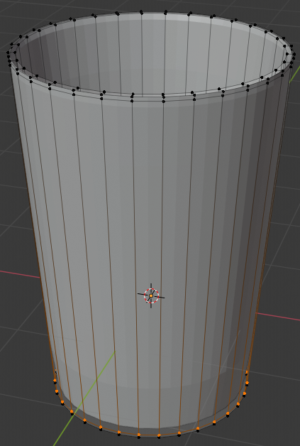
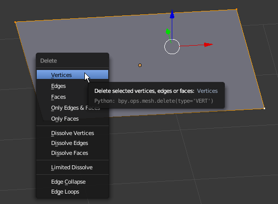
- Press X to delete
- In the menu that appears, click Vertices:
- In the Numeric Pad, press 1 (you should be in the orthogonal view; if you are not, press 5).
Also zoom in to get a bigger view
- Right-click the vertex that was left (if you don't see it, simply press A to select everything)
- Press and hold Ctrl
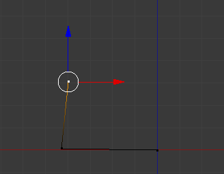
- Position the mouse on the left side by approximately 4 units and click (don't try to be precise; you will make the changes later):
- Still holding down Ctrl, position the mouse anywhere above the new vertex and click (again, don't try to be precise):
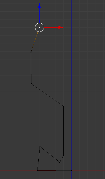
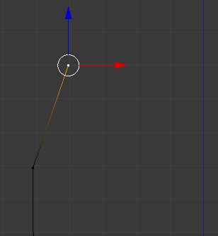
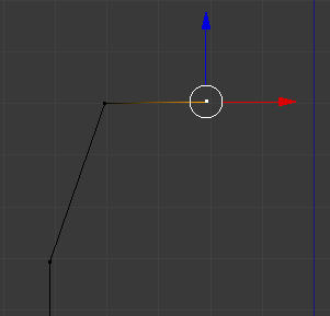
- Continue using the Ctrl key and clicking to create a shape that looks approximately as follows. Don't follow exactly the following illustration. You will make any changes later:
- To select a vertex, you can right-click it. Here is an example:
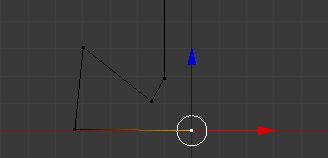
- To select many vertices, first select one of them, press and hold Shift, then right-click the other desired vertices, and release Shift
- To move a vertex, first select it. Then, either use the axes arrows and move them, or press G, move the mouse to the desired area, and click. Here is an example:
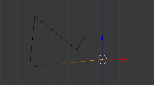
- To move many vertices, first select them, then either use the G key or the arrows to move them
- To create a new vertex, first select one on one end. Then, either hold down the Ctrl key and click in the desired area, or press E, move the mouse to the desired area, and click. Here is an example:
- To segment a line with one cut (or to create a cut), press Ctrl + R, position the mouse on the edge to be segmented until you see a dertex on it. Here is an example:
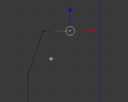
- Then click. Here is an example:
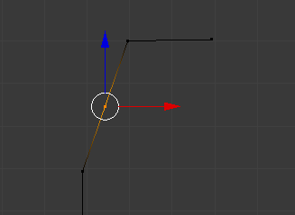
- To create many cuts, press Ctrl + R until you see an orange line on the line, then roll the middle mouse button to specify the number of cuts, then click
- Based on these techniques, create a shape approximately as follows (yours doesn't have to be exactly like the following shape; we are trying to model a glass, so use your own imagination/inspiration and taste):
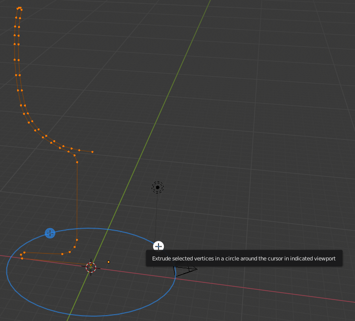
- Press Shift + S
- In the menu that appears, click Cursor to Center
- Press A to select all vertices:
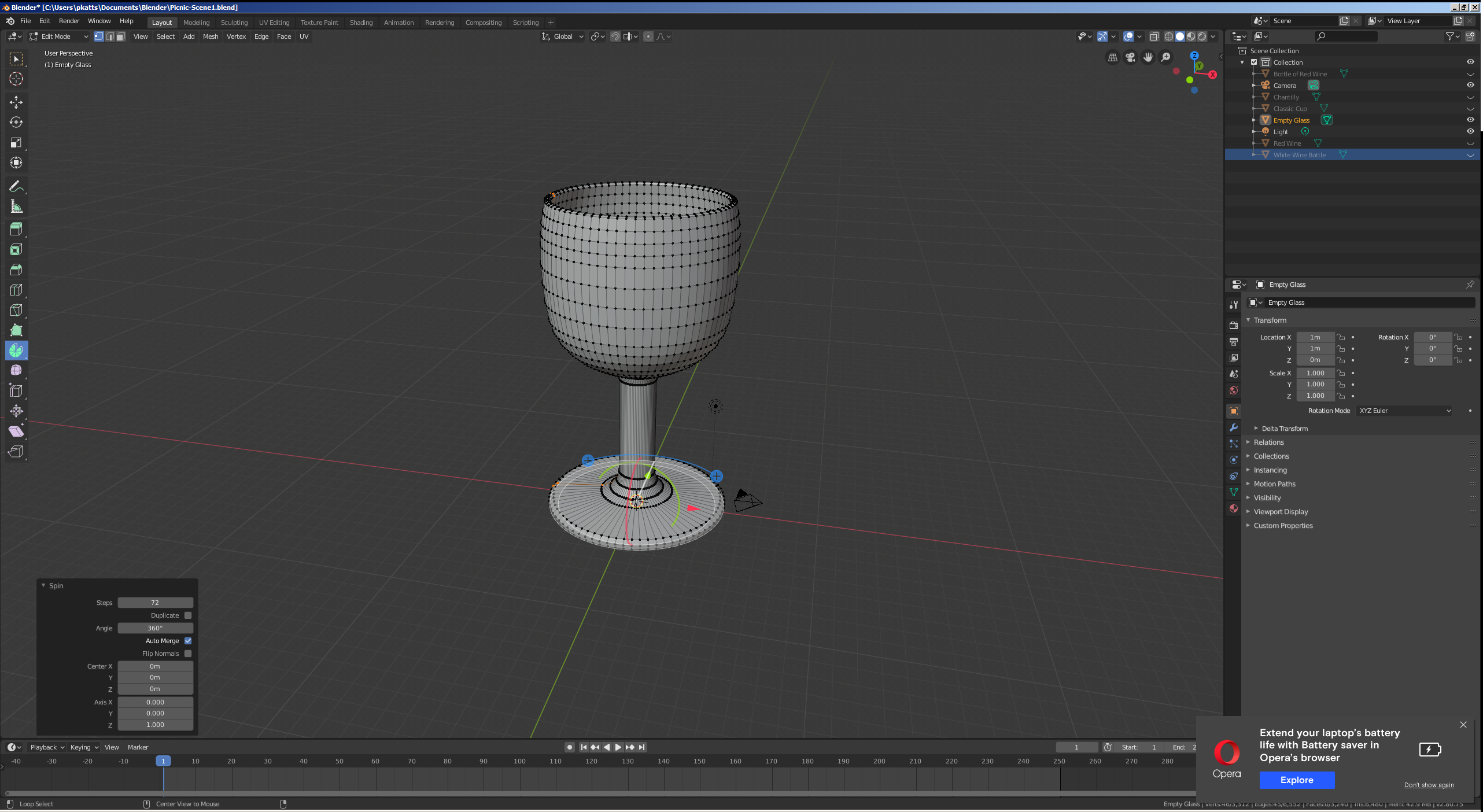
- In the Numeric Pad, press 7 to display the top view
- In the Tools menu, click the Tools tab and, in the Add section, click Spin
- In the Spin section below the Tools window, change the collowing values:
Steps: 72
Angle: 360
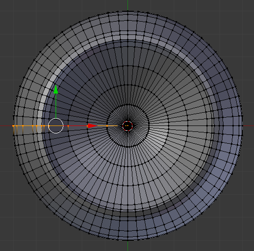
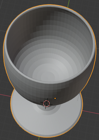
- Move the view to see the glass in perspective:
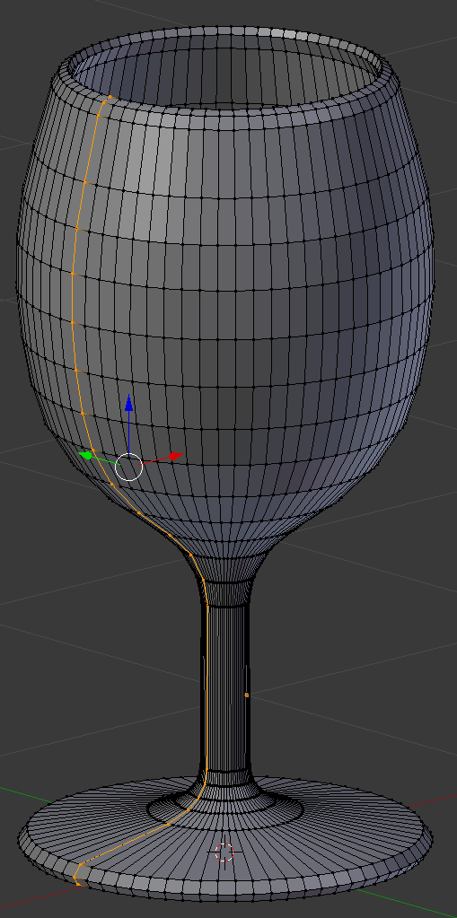
- On the menu bar of the 3D View, click Edit Mode and click Object Mode:
- In the Properties window, click the Modifiers button
- Click Add Modifier and click Subdivision Surface
- Set the View value to 2
- In the Tools window, click the Tools tab and click Smooth
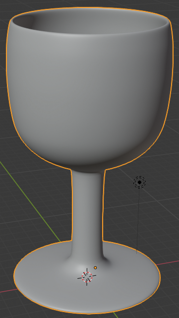
- In the Object tab of the Properties window, change the following values:
Location - X: 4.025
		     Y: -.8
           Z: 3.1825
Scale    - X: .75
		   Y: .75
           Z: .75
- In the Outliner, click the Restricted Viewport Visibility button on the right side of Empty Glass to hide it
- In the Outliner, click the Restricted Rendering button on the right side of Empty Glass
 Practical Learning: Creating an Ice Bucket
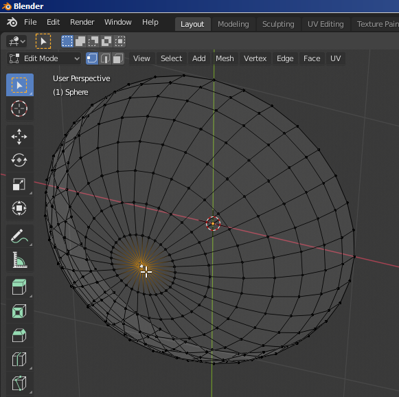
- On the menu bar of the 3D View, click Add -> Mesh -> UV Sphere
- In the Numeric Pad, press 1 (the sphere should be in orthographic view; if that's not the case,. press 5)
- Zoom in to see a larger view of the sphere
- Press Tab to display the sphere in Edit Mode
- Press A to deselect everything
- Press Z to display the sphere in wireframe
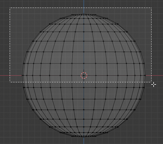
- Press B to prepare to box-select
- Draw a rectangle that selects the top portion of the sphere, including the middle line:
- Release the mouse:
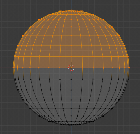
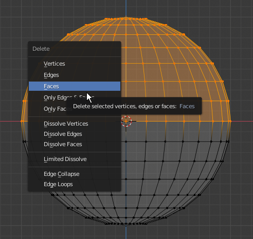
- Press X to delete
- In the menu that appears, click Faces:
- Move the view so you can see the bottom side of the object
- The Vertex Select should be On (if you have doubt, on the menu bar of the 3D-View, click the Vertex Select button
 )
)
Right-click the central-bottom vertex of the shape:
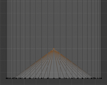
- Press G to move the vertex
- Press Z to move vertically
- Type .02 and press Enter
- In the Numeric Pad, press 1
- Press B to box-select
- Draw a rectangle that selects the group of bottom vertices:
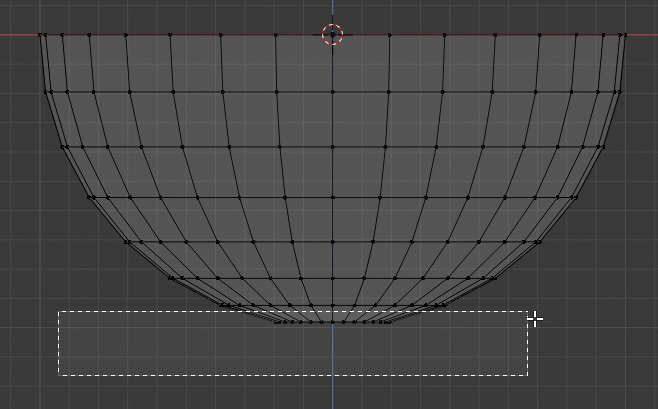
- Press G
- Press Z
- Type .06 and press Enter
- Press B to box-seect
- Draw a rectangle that selects the group of bottom vertices:
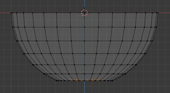
- Press G
- Press Z
- Type .1 and press Enter:
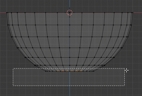
- Press Z to exit the wireframe
- Press Tab to display the shape in Object Mode:
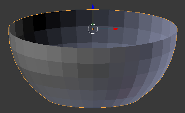
- In the Properties window, click the Object button

- Click Sphere to select it
- Type Ice Bucket and press Enter
- In the Properties window, click the Modifiers button

- Click Add Modifier and click Solidify:

- Click the Thickness value, type .05 and press Enter
- Click Apply
- Click Add Modifier and click Subdivision Surface
- Set the View to 2
- Click Apply
- In the Tools tab of the Tools window, in the Shading section, click Smooth:
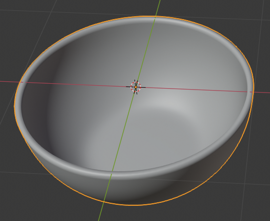
- In the Object tab of the Properties window, change the following values:
Location - X: -1.18
	   Y: -1.4
           Z: 4.03
- Position the mouse in the work area and press R to rotate
- Press Z to rotate it horizontally
- Type 35 and press Enter
- In the Outliner, click the Restricted Viewport Visibility button (the eye) on the right side of Ice Bucket to hide it
- In the Outliner, click the Restricted Rendering button on the right side of Ice Bucket
 Practical Learning: Creating a Champaign Bucket
- Position the mouse in the work area, press Shift + A -> Mesh -> Cone
- In the Add Cone section below the Tools window, change the following value:
Radius 1: .85
Radius 2: 1
- In the Object tab of the Properties window, change the following values:
Name:      Champaign Bucket
Location - X: -3.5
	   Y: 1.285
           Z: 4.22
Scale    - Z: 1.05
- Position the mouse in the work area and press tab to display the cone in Edit Mode
- Press Ctrl + R to create a horizontal cut
- Click once to confirm
- Press Z to move it vertically
- Type .9 and press Enter to move down
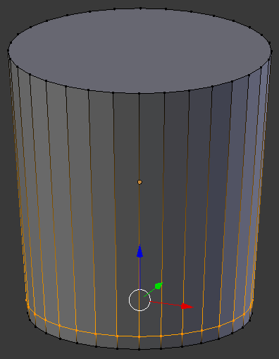
- Position the mouse below the top border and press Ctrl + R to create a horizontal cut
- Click once to create the cut
- Press Z to move it vertically
- Type .75 and press Enter to move down:
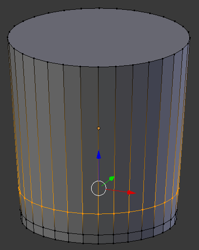
- Position the mouse below the top border and press Ctrl + R to create a horizontal cut
- Click once to create the cut
- Press Z to move it vertically
- Type .85 and press Enter:
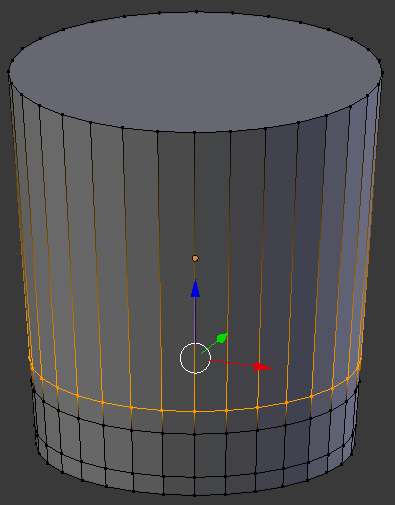
- Position the mouse below the top border and press Ctrl + R to create a horizontal cut
- Click once to create the cut
- Press Z to move it vertically
- Type .65 and press Enter:
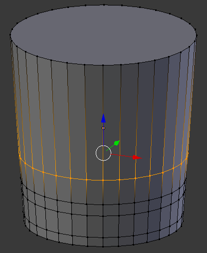
- Press Ctrl + Tab
- In the menu that appears, click Face
- Press and hold Alt
- Right-click one of the middle faces
- Release Alt:
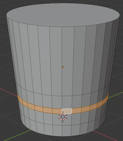
- Press S to resize
- Type .75 and press Enter:
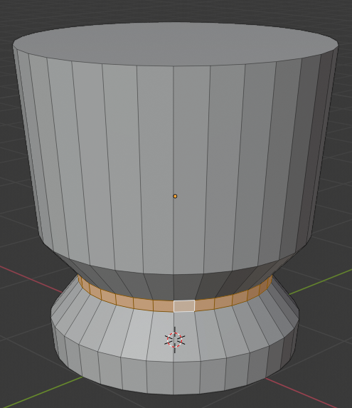
- Position the mouse below the selected faces and press Ctrl + R to create a horizontal cut
- Click twice to create the cut:
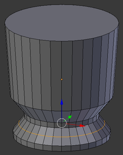
- Press S to resize
- Type .95 and press Enter
- Position the mouse above the faces that were selected and press Ctrl + R to create a horizontal cut
- Click twice to create the cut:
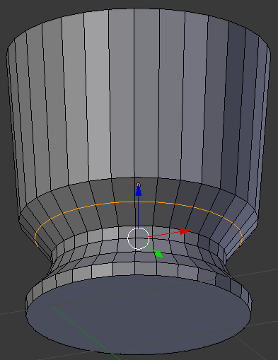
- Press S to resize
- Type .925 and press Enter:
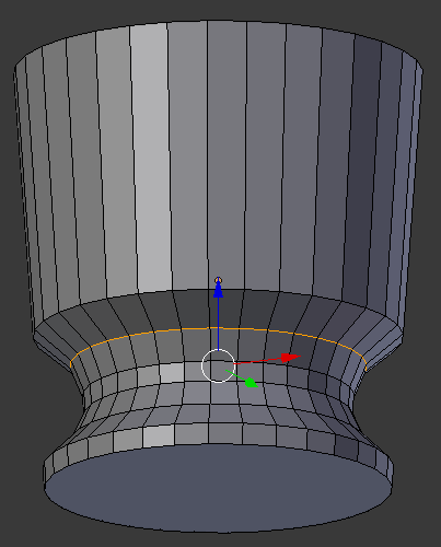
- Press Ctrl + Tab
- In the menu that appears, click Face
- Right-click the top face to select it
- Press E to extrude and press Enter
- Press G
- Press Z
- Type .1 and press Enter
- Press S to resize
- Type 1.05 and press Enter::
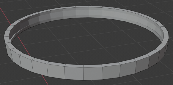
- Press E to extrude and press Enter
- Press G
- Press Z
- Type .1 and press Enter
- Press S to resize
- Type 1.1 and press Enter:
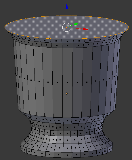
- Press X
- In the menu that appears, click Faces
- Press Tab to display the bucket in Object Mode
- In the Properties window, click the Modifiers button
- Click Add Modifier and click Solidify
- Set the Thickness value to .05
- Still in the Properties window, click Apply
- Position the mouse in the work area and press Tab to display the bucket in Edit Mode
- Position the mouse in the work area, press Shift + A -> Cone
- In the Add Cone section below the Tools window, change the following values:
Radius 1:  1.02
Radius 2:  1.04
Depth:     .2
Location - X: -3.5
		     Y: 1.285
           Z: 5.5
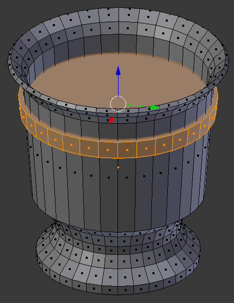
- Use the green or the red arrow to move the cone away from the bucket. Here is an example:
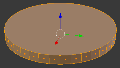
- Right-click the top face to select it
- Press E to extrude and press Enter
- Press S to resize
- Type .95 and press Enter:
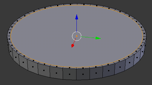
- Press X to delete
- In the menu that appears, click Faces
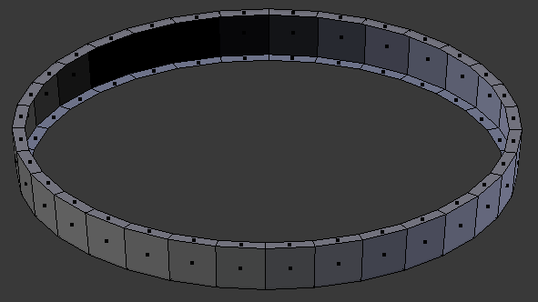
- Right-click the other inside face to select it
- Press E to extrude and press Enter
- Press S to resize
- Type .95 and press Enter
- Press X to delete
- In the menu that appears, click Faces:
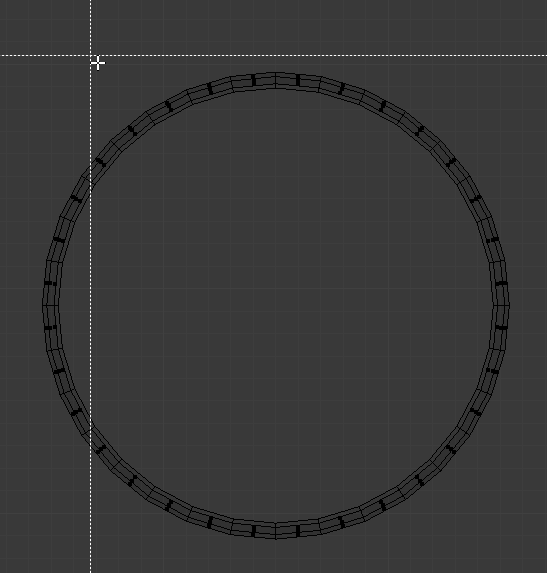
- In the Numeric Pad, press 7 to display the top view
- Press Z to display the wireframe
- Press B to prepare to box-select
- Draw a rectangle that covers some central parts of the object:
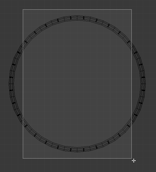
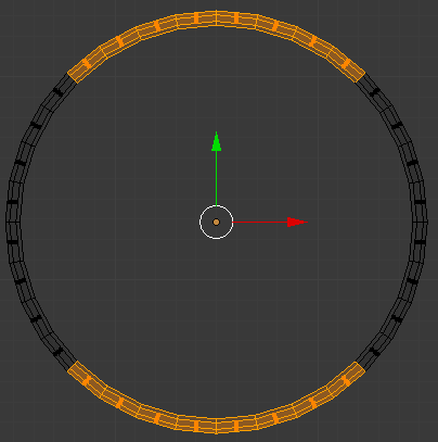
- Press X to delete
- In the menu that appears, click Faces
- Move the view so you can see the objects in perspective
- Press Z to display the objects in Solid view:
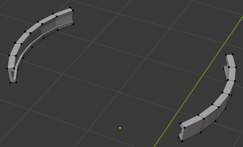
- On the menu bar of the 3D-View, click the Edge Select button

- Right-click a small edge on one side
- Press and hold Shift
- Right-click the small edge opposing it
- Release Shift:
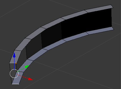
- Press F to create a face
- In the same way, create a face of the edges on the other side:
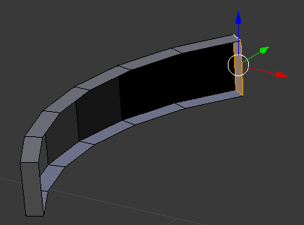
- Also create faces on the other object:
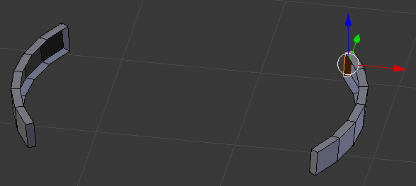
- Press Z to display the wireframe
- Press B to box-select
- Draw a rectangle that covers both objects to select them:
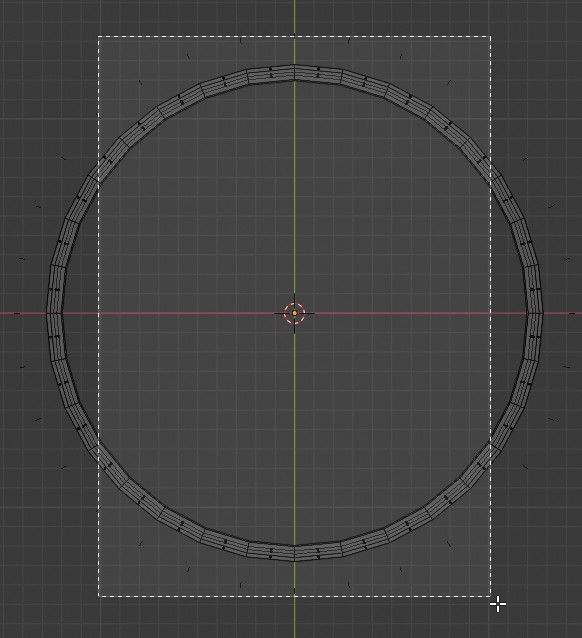
- Press Z to display the object in Solid view
- Use the green or red arrow to move the objects to the bucket:
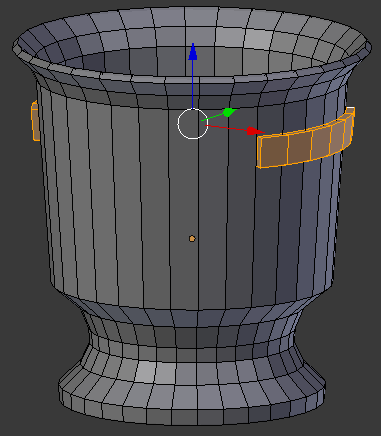
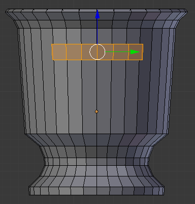
- Position the mouse in the work area, press Shift + A -> Torus
- In the Add Torus sectiom below the Tools window, change the following values:
Major Radius:  .3
Minor Radius:  .02
- If necessary, move the torus to an isolated area away from any other shape.
In the Numeric Pad, press 7 to display the top view:
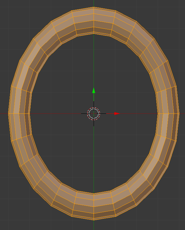
- While (make sure) all faces of the handle are selected, press S to resize
- Press Y to resize horizontally
- Type 1.65 and press Enter
- Press S to resize
- Press Z to resize horizontally
- Type 2 and press Enter
- Press A to deselect everything
- Press Z to display in wireframe
- Press B to prepare to box-select
- Draw a rectangle that covers the edges from the left to the center, including the edges in the middle:
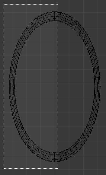
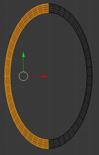
- Press X
- In the menu that appears, click Faces
- Press B again and select all edges of the object that was created
- Press Z to display the objects in Solid View
- Move the view to display the objects in perspective
- Move the torus to the root handle that was glued to the bucket (when placing the handle, look inside the bucket and make sure the handle doesn't come out inside). Here is an example:
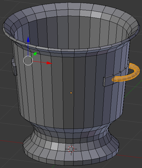
- Make sure (all faces of) the right handle is (are) selected (if you have doubts, prress A to deselect everything, then position the mouse on the right handle, and press L).
Press Shift + D to copy
- Press X to move the handle horizontally
- Move the mouse/handle away from the bucket and click
- Press R to rotate the handle
- Press Z to rotate it vertically
- Type 180 and press Enter
- Move the handle to the left side of the bucket:
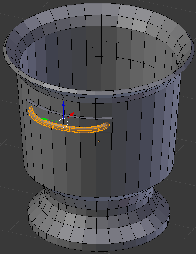
- Press Tab to display the bucket in Object Mode
- In the Modifiers section of the Properties window, click Add Modifier and click Subdivision Surface
- Set the View to 2
- Position the mouse in the work area and press Tab to work in Edit Mode
- Press Ctrl + R to create some cuts and position them as follows:
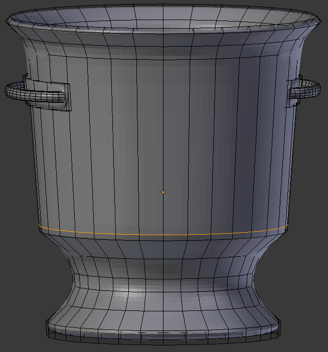
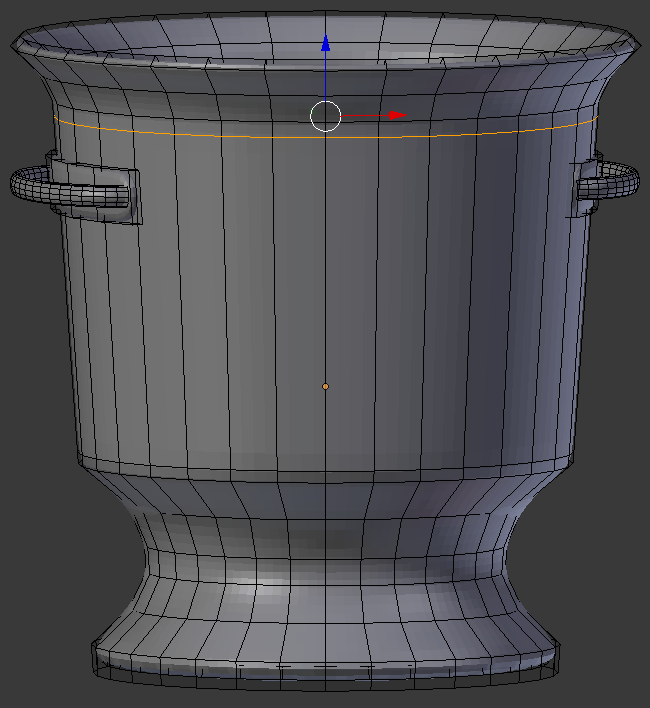
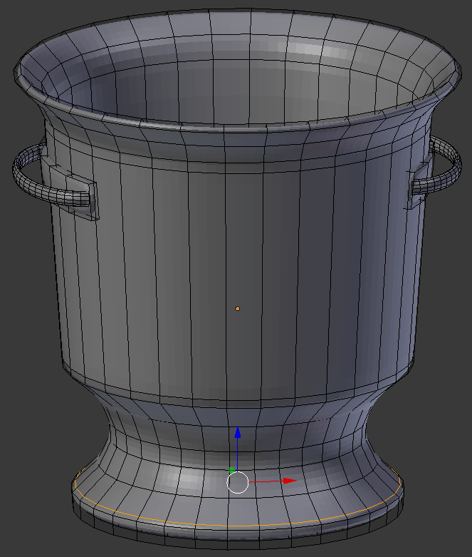
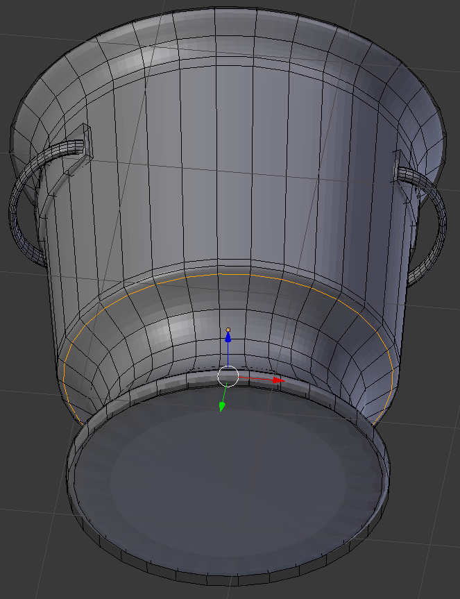
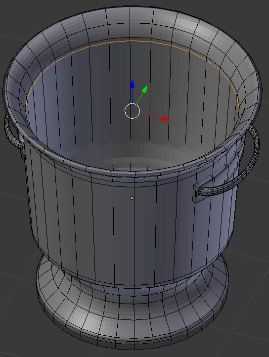
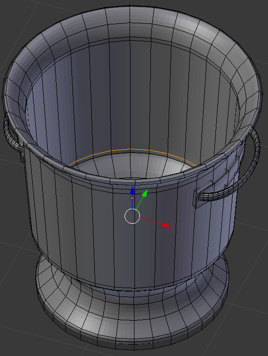
- Press Tab
- In the Propertties window, click Apply
- In the Tools tab of the Tools window, in the Shading section, click Smooth:
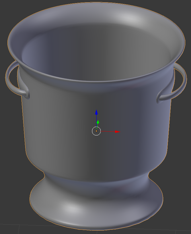
- Position the mouse in the work area and press R to rotate the bucket
- Press Z to rotate it horizontally
- Type 35 and press Enter
- In the Outliner, click the Restricted Viewport Visibility button on the right side of Champaign Bucket to hide it
- In the Outliner, click the Restricted Rendering button on the right side of Champaign Bucket
 Practical Learning: Creating a Picnic Table
- Position the mouse in the work area, press Shift + A -> Mesh -> Cube
- In the Properties window, click the Object button

- In the Transform section, change the following values:
name:      Table Board
Location - X: 0
		     Y: 0
		     Z:  3.1
Scale    - X: 5
		     Y: .75
		     Z: .1
- Position the mouse in the work area, press Alt + D to duplicate, and press Enter
- In the Properties window, below Location, click the Y value, type -1.6 and press Enter
- Position the mouse in the work area, press Alt + D to copy, and press Enter
- In the Properties window, change the Y value of the Location to 1.6 and press Enter:
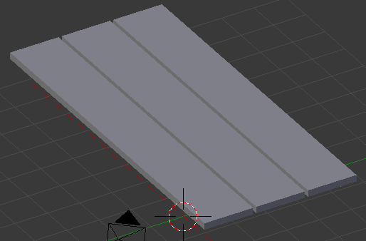
- Position the mouse in the work area, press Alt + D, and press Enter
- In the Properties window, change the following values:
Location - Y: -3.2
	   Z: 1.6
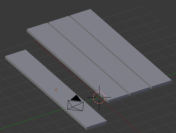
- Position the mouse in the work area, press Alt + D to copy, and press Enter
- In the Properties window, change the Y value of the Location to 3.2 and press Enter
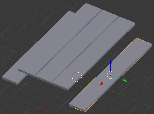
- Position the mouse in the work area.
Press Alt + D and press Enter
- In the Object section of the Properties window, change the following values:
Location - X: 3.25
           Y: 0
		     Z:  2.85
Scale    - X: .1
		     Y: 2.35
		     Z: .15
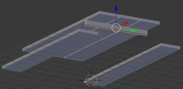
- Position the mouse in the work area, press Alt + D, and press Enter
- In the Properties window, under Location, click the X value, type -3.25 and press Enter
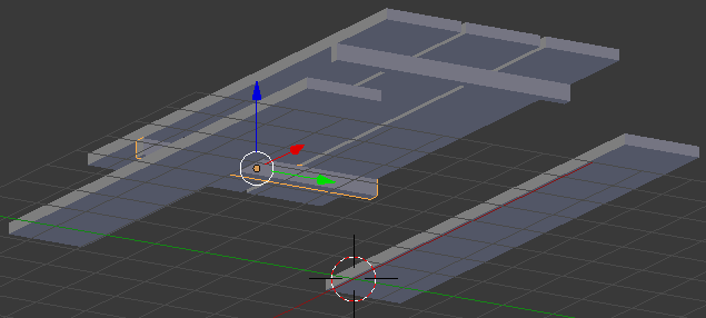
- Position the mouse in the work area, press Alt + D, and press Enter
- In the Properties window, change the following values:
Location - Z: 1.35
Scale    - Y: 4
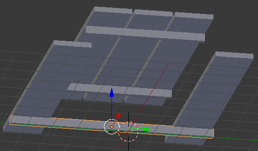
- Position the mouse in the work area, press Alt + D, and press Enter
- In the Properties window, under Location, click the X value, type 3.25 and press Enter:
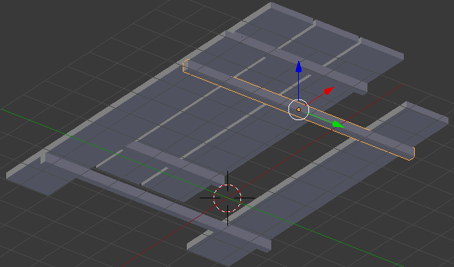
- In the Create section of the Tools tab, click Cylinder
- In the Object tab of the Properties window, change the following values:
Name:      Table Leg
Location - X: 3
		     Y: -3.25
		     Z: .75
Scale    - X: .15
		     Y: .15
		     Z: .75
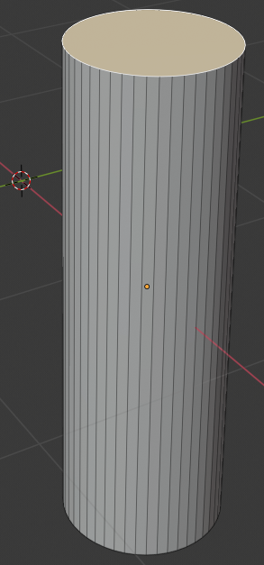
- Position the mouse in the work area, press Alt + D, and press Enter
- In the Properties window, under Location, click the X value, type -3 and press Enter:
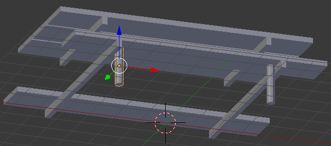
- Position the mouse in the work area, press Alt + D, and press Enter
- In the Properties window, change the Y location to 3.25
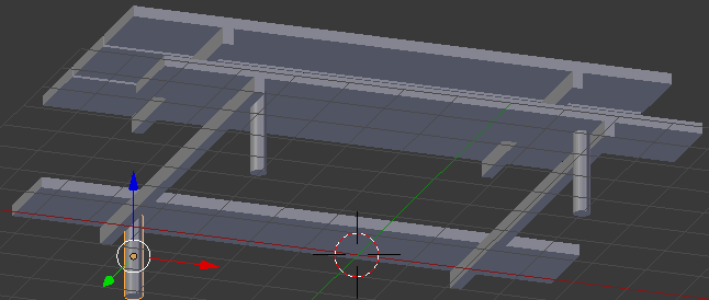
- Position the mouse in the work area, press Alt + D, and press Enter
- In the Properties window, change the X location to 3 and press Enter:
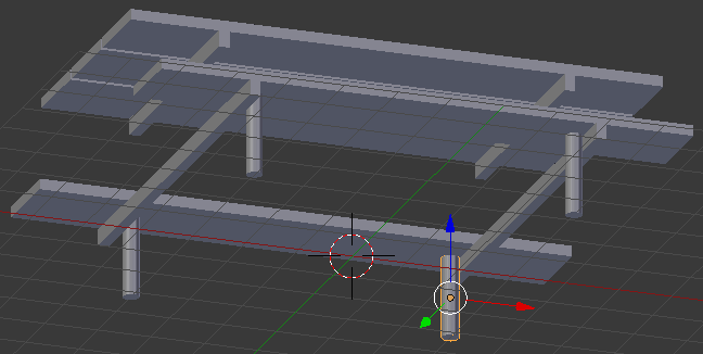
- Position the mouse in the work area, press Alt + D, and press Enter
- In the Properties window, change the following values:
Location - Y: -1.5
		     Z: 1.5
Scale    - Z: 1.5
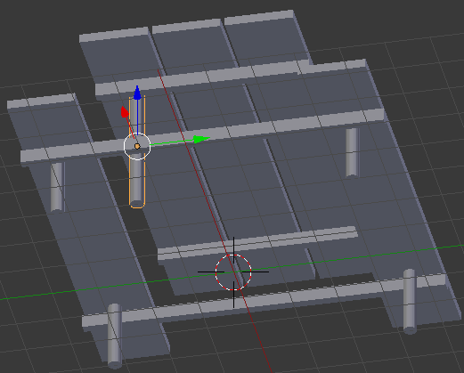
- Position the mouse in the work area, press Alt + D, and press Enter
- In the Properties window, change the Y location to 1.5 and press Enter
- Position the mouse in the work area, press Alt + D, and press Enter
- In the Properties window, change the X location to -3 and press Enter
- Position the mouse in the work area, press Alt + D, and press Enter
- In the Properties window, change the Y location to -1.5 and press Enter:

 Practical Learning: Creating Ice Cubes
- In the Outliner, click the Restricted Viewport Visibility button (the eye) on the right side of Ice Bucket to display it
- In the Create tab of the Tools window, click Cube
- In the Object tab of the Properties window, change the following values:
Name:      Ice Cube
Location - X: -1
		     Y: -1.5
           Z: 7
Scale    - X: .1
		     Y: .1
           Z: .1
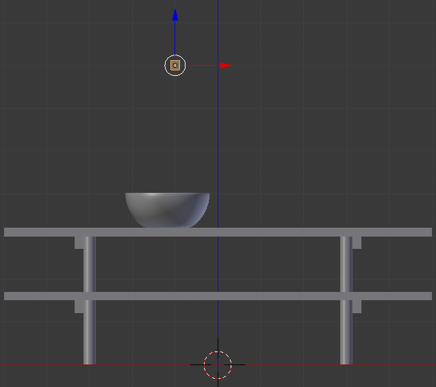
- In the Tools window, click the Physics tab
- In the Add/Remove section, click Add Active
- In the Properties window, click the Modifiers button
- Click Add Modifier and click Bevel
- Click the Width value, type .25 and press Enter:
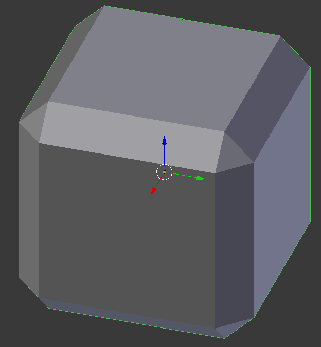
- Click Apply
- In the Properties window, click the Object button

- In the Numeric Pad, press 1 to access the front view
- Position the mouse in the work area. Press Alt + D and press Enter
- Use the blue arrow of the Z axis to move the new ice cube above the first one
- In the Numeric Pad, press 3
- Use the green arrow of the Y axis to move the ice cube slightly to the left or the right of the other. Here is an example:
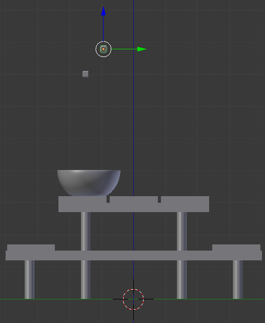
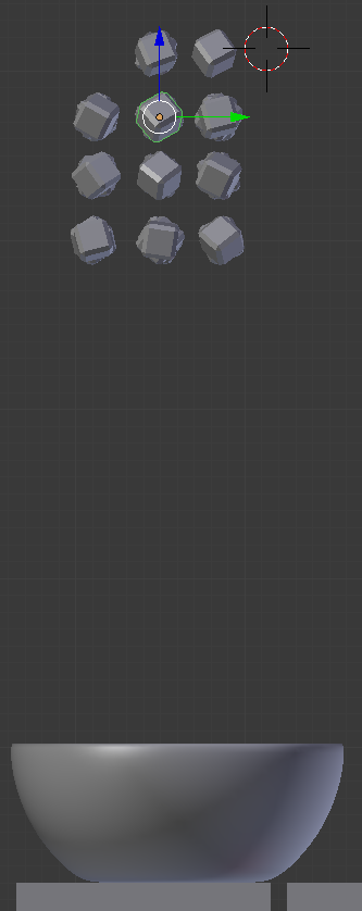
- Press Alt + D and press Enter about 40 times (it doesn't have to be exactly 40 times; we just need a few cubes but we can't create them through the Array modifier)
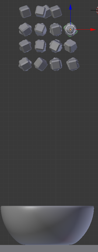
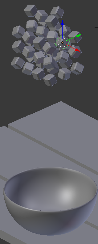
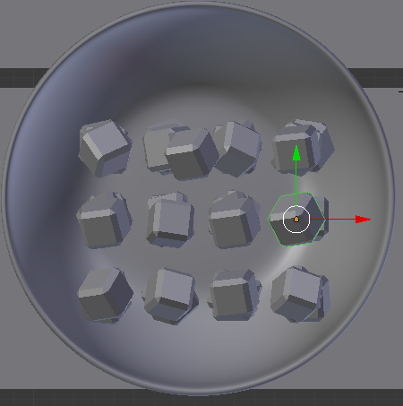
- Right-click a cube to select it, move it. Change to the side view, the front view, and the top view. Use the Rotate button on the menu bar of the 3D View to rotate the cube. Visually keep all ice cubes within the circumference of the top face of the ice bucket. Create the group of cubes approximately as follows (your design doesn't have to match the following one):
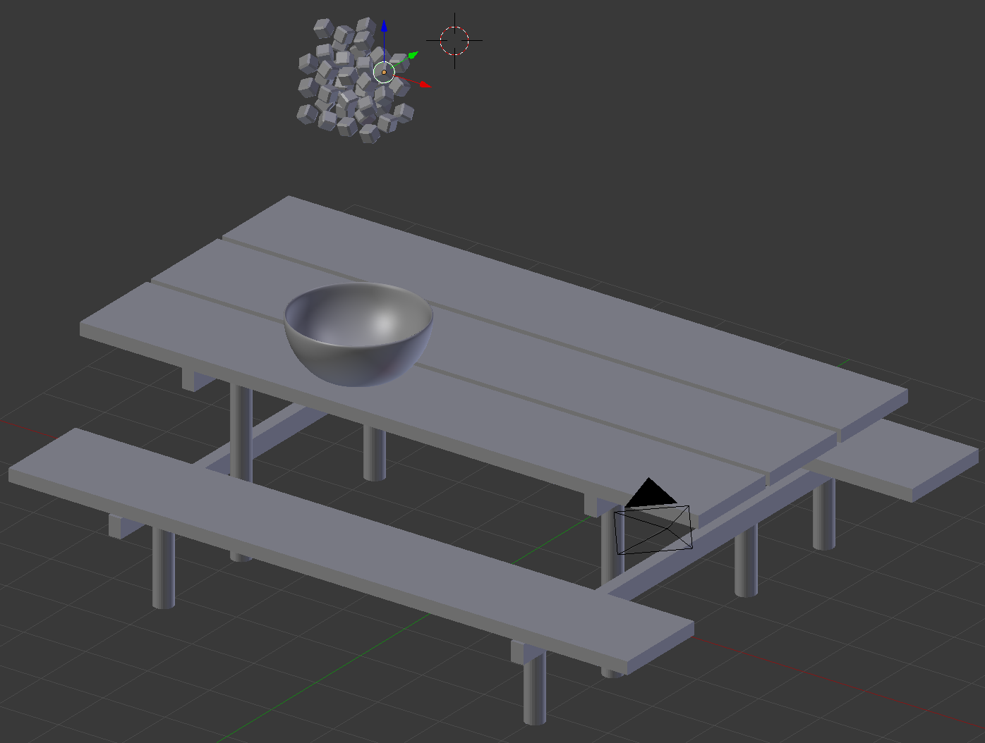
- In the work area, right-click the ice bucket to select it
- In the Tools window, click the Physics tab
- In the Add/Remove section, click Add Passive
- In the Outliner, click the Restrict Viewport Visibility button (the eye) on the right side of Ice Bucket) to hide it
 Practical Learning: Creating A Horizon
- In the Tools window, click the Create tab
- In the Create tab of the Tools window, click Plane
- In the Object tab of the Properties window, change the following values:
Name:      Horizon
Location - X: -15
		     Y: 20
		     Z: 0
Scale    - Z: 35
		     Y: 40
 Practical Learning: Creating the Borders of the Eating Area
- In the Create tab of the Tools window, click Cube
- In the Object tab of the Properties window, change the following values:
Name:      Eatery Border - Front
Location - X: 0
		     Y: -8.5
		     Z: 0
Scale    - X: 8.5
		     Y: .2
           Z: .1
- Position the mouse in the work area, press Alt + D, and press Enter
- In the Properties window, change the Y location to 8.5
- In the Create tab of the Tools window, click Cube
- In the Object tab of the Properties window, change the following values:
Name:      Eatery Border - Left
Location - X: -8.3
		     Y: 0
		     Z: 0
Scale    - X: .2
		     Y: 8.3
           Z: .1
- Position the mouse in the work area, press Alt + D, and press Enter
- In the Properties window, change the X location to 8.3
 Practical Learning: Adding an Eating Area
- In the Create tab of the Tools window, click Plane
- In the Object tab of the Properties window, change the following values:
Name:      Eating Area
Location - X: 0
		     Y: 0
		     Z: .075
Scale    - X: 8.25
		     Y: 8.5
 Practical Learning: Introducing Materials
- On the top menu bar, click Blender Render and, in the menu that appears, click Cycles Render
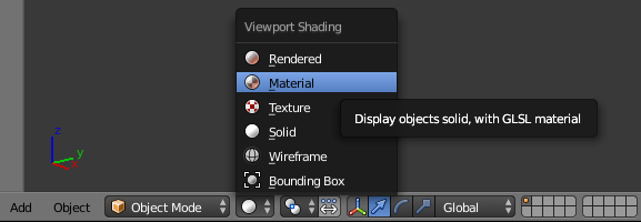
- On the menu bar of the 3D View, click the Viewport Shading button and select Material:
- In the Properties window, click the Render button

- Below Resolution, click 50% to select it
- Type 100 and press Enter
- Click Sampling to expand it
- Change the value of Render to 2000 and press Enter
- In the Properties window, click the World button

- Click Use Nodes
- Click the Color button and click RGB
- Set the RGB values as follows:
R: .985
G: .945
B: .875
- Position the mouse in the small triangle in the top-right corner of the 3D View until the cursor becomes a +:
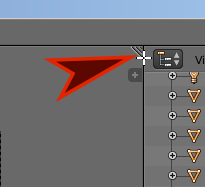
- Click and drag down roughly a third of the height of the screen
- Release the mouse to create the window
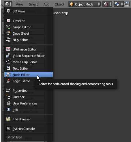
- Click the button in the bottom-left section of the new window and click Node Editor:
- In the Properties window, click the Material button

Material Mixing
Blender provides various ways to combine materials to get a special effect or a particular appearance. Probably the most fundamental technique consists of using a material or feature named Mix Shader. The window of this material is equipped with two entry source. You can use each of these entries to include a material of your choice. Obviously each input should be different.
 Practical Learning: Materializing the Table Border
- In the Outliner, click Table Board to select it
- In the Material tab of the Properties window, click the New button
- In the Node Editor, click in the Diffuse window to give it focus
- Press X to delete it
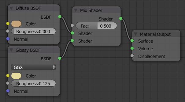
- On the menu bar of the Node Editor, click Add -> Shader -> Mix Shader
- Position the mouse on the left side of the Material Output window and click
- From the Mix Shader window, drag the green button on the right border of the window and drop it on the green Surface button of the Material Output window
- Position the mouse in the Node Editor.
Press Shift + A -> Shader -> Diffuse BSDF
- Position the mouse on the top-left side of the Mix Shader window and click
- Drag the green button from the Diffuse BSDF window and drop it on the top green Shader button on the left side of the Mix Shader window
- In the Diffuse BSDF window, click the Color button and click RGB
- Set the RGB values as follows:
R: .562
G: .372
B: .191
- Position the mouse in the Node Editor.
Press Shift + A -> Shader -> Glossy BSDF
- Position the mouse below the Diffuse BSDF window and click
- Drag the green button from the Glossy BSDF window and drop it on the bottom green Shader button on the left side of the Mix Shader window
- In the Glossy BSDF window, click the Color button
- Set the RGB values as follows:
R: .800
G: .7
B: .34
- Still in the Glossy BSDF window, click the Roughness number to select it
- Type .125 and press Enter:
- Position the mouse on the work area and, in the Numeric Pad, press 0 to display the camera view
- Press N to display the Properties Region
- In the Properties Region, click Lock Camera to View to put a check box on it
- Use the mouse and keyboard to display the view any way you want (for this example, I used the Restrict Viewport Visibility and the Restrict Rendering buttons of each ice cube to hide them). Here is an example:

- In the Properties Region, click Lock Camera to View to remove the check box
- On the top menu, click Render and click Render Image:

- On the menu bar of the UV/Image Editor, click View and click Save As Image
- Set the file name as Picnic Table1 and click Save As Image
- To return to the modeling scene, press Esc
 Practical Learning: Materializing a Champaign Bucket
- In the Outliner, click the Restricted Rendering button (the camera) on the right side of Champaign Bucket to make it available for rendering
- In the Outliner, click the Restrict Viewport Visibility button on the right side of Champaign Bucket to display it
- In the Outliner, click Champaign Bucket to select it
- In the Properties window, click the New button
- In the Properties window, click Diffuse BSDF
- In the menu that appears, click Mix Shader
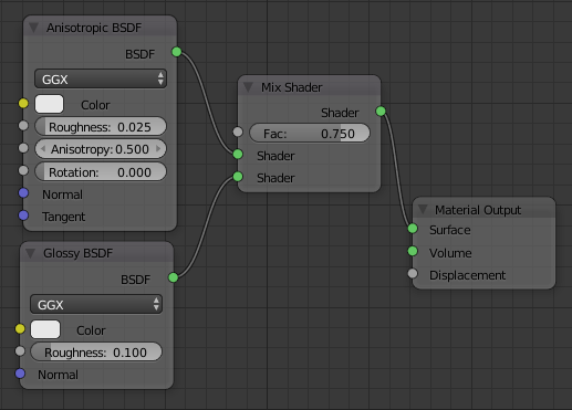
- On the menu bar of the Node Editor, click Add -> Shader -> Anisotropic BSDF
- Position the mouse on the top-left of the Mix Shader and click
- Drag the green button from Anisotropic BSDF and drop it on the top Shader button of the Mix Shader window
- On the menu bar of the Node Editor, click Add -> Shader -> Glossy BSDF
- Position the mouse below the Anisotropic BSDF window and click
- Drag the green button from Glossy BSDF and drop it on the bottom Shader button of the Mix Shader window
- In the Mix Shader window, click the value of Fac to select it
- Type .75 and press Enter
- Click the Roughness value in the Anisotropic BSDF window to select it
- Type .025 and press Enter
- In the same way, in the Glossy BSDF window, set the Roughness value to .1:
- Position the mouse on the work area and, in the Numeric Pad, press 0 to display the camera view
- Press N to display the Properties Region
- In the Properties Region, click Lock Camera to View to put a check box on it
- Use the mouse and keyboard to display the view any way you want (for this example, I used the Restrict Viewport Visibility and the Restrict Rendering buttons of each ice cube to hide them). Here is an example:

- In the Properties Region, click Lock Camera to View to remove the check box
- On the top menu, click Render and click Render Image:

- On the menu bar of the UV/Image Editor, click View and click Save As Image
- Set the file name as Champaign Bucket and click Save As Image
- To return to the modeling scene, press Esc
Using an Input When Mixing Materials
You are probably familiar with techniques of adding values to materials in Blender. These techniques can involve such items as colors or roughness. Other techniques involve such items as textures. The techniques used to add a value that includes an input such as a value or a texture can also be used when mixing some materials.
 Practical Learning: Materializing a Bottle of Red Wine
- In the Outliner, click the Restrict Viewport Visibility button on the right side of Bottle of Red Wine to display it
- In the Outliner, click the Restricted Rendering button on the right side of Bottle of Red Wine
- In the Outliner, click Bottle of Red Wine to select it
- On the toolbar of the Node Editor, click the New button
- In the Properties window, click Diffuse BSDF
- In the menu that appears, click Mix Shader

Notice that, in the Node Editor, the Diffuse BSDF window has been replaced by the Mix Shader window
- In the Properties window, click the top None button (of the top Shader) and click Glass BSDF:
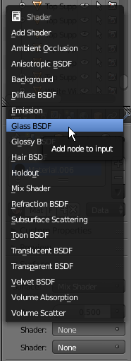
- In the Properties window, click the bottom None and select Diffuse BSDF
- On the menu bar of the Node Editor, click Add -> Input -> Value
- Click the left side of the Glass BSDF window to position the Value window
- Drag the gray Value button from the Value window and drop it on the gray Roughness value of the Glass BSDF window
- In the Value window, click the Value value to select it
- Type .005 and press Enter
- Position the mouse in the Node Editor and press Shift + A -> Input -> RGB
- Click the left side of the Diffuse BSDF to position the new window
- In the RGB window, click the horizontal bar below the color wheel and set the color as follows:
R: .395
G: .225
B: .185
- Drag the yellow Color button from the RGB window to the yellow button from the Diffuse BSDF window:

- Position the mouse on the work area and, in the Numeric Pad, press 0 to display the camera view
- Press N to display the Properties Region
- In the Properties Region, click Lock Camera to View to put a check box on it
- Use the mouse and keyboard to display the view any way you want. Here is an example:

- In the Properties Region, click Lock Camera to View to remove the check box
- In the Node Editor, in the Mix Shader window set the value of the Fac to .005
- On the top menu, click Render and click Render Image:

- On the menu bar of the UV/Image Editor, click View and click Save As Image
- Set the file name as Empty Bottle1 and click Save As Image
- To return to the modeling scene, press Esc
- In the Node Editor, in the Mix Shader window set the value of the Fac to .225
- On the top menu, click Render and click Render Image:

- On the menu bar of the UV/Image Editor, click View and click Save As Image
- Set the file name as Empty Bottle2 and click Save As Image
- To return to the modeling scene, press Esc
 Practical Learning: Materializing an Empty Bottle
- In the Outliner, click the Restrict Viewport Visibility button on the right side of Chantilly to display it
- In the Outliner, click the Restricted Rendering button on the right side of Chantilly
- In the Outliner, click Chantilly bottle to select it
- In the Material tab of the Properties window, click the New button
- In the Node Editor, click Diffuse BSDF to select its window
- Press X to delete the window
- In the Material tab of the Properties window, on the right side of Surface, click None
- On the menu that appears, click Mix Shader.
Notice that, in the Node Editor, a Mix Shader window has been added and attached to the Material Output window
- On the menu bar of the Node Editor, click Add -> Shader -> Glass BSDF
- Position the mouse on the top-left side of the Mix Shader window and click
- On the menu bar of the Node Editor, click Add -> Input -> RGB
- Position the mouse on the left side of the Glass BSDF window and click
- In the RGB window, click the horizontal bar below the color wheel and set the RGB value as follows:
R: .675
G: 1
B: .515
- Drag the yellow button from the RGB window and drop it on the yellow button of the Glass BSDF window
- Drag the green button from the Glass BSDF window and drop it on the top green Shader button of the Mix Shader window
- In the Material section of the Properties window, click the bottom None button and, in the menu that appears, click Diffuse BSDF.
In the Node Editor, notice that a Diffuse BSDF window has been added and it got attached to the second Shader button of the Mix Shader window
- On the menu bar of the Node Editor, click Add -> Input -> Value
- Position the mouse on the left side of the Diffuse BSDF window and click
- In the Value window, click the value to select it
- Type .25 and press Enter
- In the Node Editor, drag the gray button from the Value window and drop it on the gray button (Roughness) of the Diffuse BSDF window

- Position the mouse on the work area and, in the Numeric Pad, press 0 to display the camera view
- Press N to display the Properties Region
- In the Properties Region, click Lock Camera to View to put a check box on it
- Use the mouse and keyboard to display the view any way you want. Here is an example:

- In the Properties Region, click Lock Camera to View to remove the check box
- On the top menu, click Render and click Render Image:

- On the menu bar of the UV/Image Editor, click View and click Save As Image
- Set the file name as Empty Bottle1 and click Save As Image
- To return to the modeling scene, press Esc
- In the Node Editor, in the Mix Shader window set the value of the Fac to .015
- On the top menu, click Render and click Render Image:

- On the menu bar of the UV/Image Editor, click View and click Save As Image
- Set the file name as Empty Bottle2 and click Save As Image
- To return to the modeling scene, press Esc
 Practical Learning: Materializing a Bottle of White Wine
- In the Outliner, click the Restrict Rendering button on the right side of Bottle of White Wine to display it
- In the Outliner, click the Restrict Viewport Visibility button on the right side of Bottle of White Wine to display it
- In the Outliner, click Bottle of White Wine to select it
- In the Properties window, click the New button
- In the Node Editor, right-click any section in the Diffuse BSDF window to give it focus
- Press Delete to remove it
- Position the mouse in the Node Editor and press Shift + A -> Shader -> Mix Shader
- Click on the left side of the Material Output window to position the new window
- On the menu bar of the Node Editor, click Add -> Input -> Value
- Position the mouse on the top-left of the Mix Shader and click
- Drag the button from the Value window and drop it on the gray Fac button of the Mix Shader window
- On the menu bar of the Node Editor, click Add -> Shader -> Glass BSDF
- Position the mouse on the left of the Mix Shader and below the Value window, then click
- Drag the green button from Glass BSDF and drop it on the top Shader button of the Mix Shader window
- Position the mouse inside the Node Editor and press Shift + A -> Input -> Value
- Position the mouse on the left side of the Glass BSDF window and click
- Drag the button from the new Value window and drop it on the gray Roughness button of the Glass BSDF window
- On the menu bar of the Node Editor, click Add -> Shader -> Diffuse BSDF
- Position the mouse below the Glass BSDF window and click
- Drag the green button from the Diffuse BSDF window and drop it on the bottom Shader button of the Mix Shader window
- On the menu bar of the Node Editor, click Add -> Input -> RGB
- Position the mouse on the top-left side of the Diffuse BSDF window and click
- Drag the yellow button from the RGB window and drop it on the yellow button of the Diffuse BSDF window
- In the Node Editor, click one of the Value windows to select it
- Press Shift + D to copy
- Position the mouse below the RGB window and to the left side of the Diffuse BSDF window, then click
- Drag the button from the new Value window and drop it on the gray Roughness button of the Diffuse BSDF window
- Click the value on the left of the Glass BSDF window to select it
- Type .005 and press Enter
- On the left side of the Diffuse BSDF window, click the horizontal bar below the Color wheel and set the color as follows:
R: .875
G: .905
B: .545
- On the left side of the Diffuse BSDF window, click the value in the Value window to select it
- Type .1 and press Enter
- From the Mix Shader window, drag the green Shader button and drop it on the green Surface button of the Material Output window

- Position the mouse on the work area and, in the Numeric Pad, press 0 to display the camera view
- Press N to display the Properties Region
- In the Properties Region, click Lock Camera to View to put a check box on it
- Use the mouse and keyboard to display the view any way you want. Here is an example:

- In the Properties Region, click Lock Camera to View to remove the check box
- On the top menu, click Render and click Render Image:

- On the menu bar of the UV/Image Editor, click View and click Save As Image
- Set the file name as Empty Bottles1 and click Save As Image
- To return to the modeling scene, press Esc
- On the left side of the Diffuse BSDF window, click the horizontal bar below the Color wheel and set the color as follows:
R: 1
G: 1
B: 0
- In the Node Editor, click the value of the top Value window (connected to the Fac button of the Mix Shader) to select it
- Type .205 and pres Enter
- On the top menu, click Render and click Render Image:

- On the menu bar of the UV/Image Editor, click View and click Save As Image
- Set the file name as Empty Bottles2 and click Save As Image
- To return to the modeling scene, press Esc
Mixing Combinations of Materials
To combine materials in Blender, you can use the Mix Shader feature. With this technique, you can combine two materials using the Mix Shader window that is equipped with two input buttons. In reality, any of the input buttons can receive its own Mix Shader. This feature provides tremendous options in creating materials.
 Practical Learning: Materializing the Ice Bucket
- In the Outliner, click the Restrict Viewport Visibility button on the right side of Ice Bucket to display it
- In the Outliner, click the Restrict Rendering button on the right side of Ice Bucket to display it
- In the Outliner, click Ice Bucket to select it
- In the Properties window, click the New button
- In the Node Editor, right-click anywhere in the Diffuse widow to select it
- Press X to delete it
- On the menu bar of the Node Editor, click Add -> Shader -> Mix Shader
- Click on the left side of the Material Output window to position the window
- Drag the right green button from the Mix Shader window and drop it on the Surface button
- On the menu bar of the Node Editor, click Add -> Shader -> Glass BSDF
- Position the mouse on the top-left side of the Mix Shader window and click
- Drag the green button from the Glass BSDF window to the top green Shader button of the Mix Shader window
- Position the mouse in the Node Editor and press Shift + A -> Shader -> Mix Shader
- Position the mouse below the Glass BSDF window and click
- Drag the right green button from the left Mix Shader window and drop it on the bottom green Shader button of the right-side Mix Shader window
- On the menu bar of the Node Editor, click Add -> Shader -> Anisotropic BSDF
- Click on the top-left side of the left Mix Shader window to position the window
- Drag the green button from the Anisotropic BSDF window and drop it on the top green Shader button of the left Mix Shader window
- On the menu bar of the Node Editor, click Add -> Shader -> Diffuse BSDF
- Position the mouse below the Anisotropic BSDF window and click
- Drag the green button from the Diffuse BSDF window and drop it on the bottom green Shader button of the left Mix Shader window
- On the menu bar of the Node Editor, click Add -> Input -> Value
- Position the mouse above the Anisotropic BSDF window and click
- Drag the gray button from the Value window and drop it on the gray button of the left Mix Shader window
- In the Value window, click the value to select it
- Type .125 and press Enter
- On the menu bar of the Node Editor, click Add -> Input -> Value
- Position the mouse on the left side of the Anisotropic BSDF window and click
- In the new Value window, click the value to select it
- Type .075 and press Enter
- Drag the gray button from the left Value window and drop it on the gray Roughness button of Anisotropic BSDF

- Position the mouse on the work area and, in the Numeric Pad, press 0 to display the camera view
- Press N to display the Properties Region
- In the Properties Region, click Lock Camera to View to put a check box on it
- Use the mouse and keyboard to display the view any way you want. Here is an example:

- In the Properties Region, click Lock Camera to View to remove the check box
- On the top menu, click Render and click Render Image:

- On the menu bar of the UV/Image Editor, click View and click Save As Image
- Set the file name as Ice Vase1 and click Save As Image
- To return to the modeling scene, press Esc
- In the Node Editor, in the right Mix Shader window set the value of the Fac to .085
- On the top menu, click Render and click Render Image:

- On the menu bar of the UV/Image Editor, click View and click Save As Image
- Set the file name as Ice Vase2 and click Save As Image
- To return to the modeling scene, press Esc
- Position the mouse in the small triangle in the top-right corner of the 3D View until the cursor becomes a +
- Click and drag up until a gray arrow appears in the Node Editor
- Release the mouse to close the Node Editor
- In the Properties window, click the Material button

Completing the Materials
If you don't see some dramatic effect, you don't have to combine materials. You can use the simple classic technique that consists of selecting an object and simply applying a material to it.
 Practical Learning: Materializing the Horizon
- In the work area, right-click the large plane (alternatively, in the Outliner, click Horizon) to select it
- In the Properties window, click the New button
- Still in the Properties window, click the white button on the right side of Color
- Set the color values as follows:
R: 0
G: .205
B: 0
 Practical Learning: Materializing the Eatery Border
- In the Outliner, click Eatery Border - Front to select it
- In the Properties window, click the New button
- Double-click Material.007 to select the name
- Type Brown Wood and press Enter
- Click the white Color button and set the color as follows:
R: .205
G: .095
B: .025
- In the Outliner, click Eatery Border - Left to select it
- Click the button on the left side of New and select Brown Wood
 Practical Learning: Materializing the Eating Area
- Save the following picture to your hard drive:

- In the work area, right-click the plane inside the wood border to select it (if you are having difficulties selecting it, in the Outliner, click Eatery Area)
- In the top toolbar, click the button on the left side of Default and click Compositing
- In the Properties window, click the New button
- In the Properties window, click the dark-gray button on the right-click of Color and click Image Texture
- In the Properties window, click the Open button
- Select the pieces.png picture and click Open Image
- Position the mouse in the 3D View (in the bottom-right window titled Camera Persp) and press Tab to work in Edit Mode
- Position the mouse in the 3D View in the lower-right window and press U
- In the menu that appears, click Unwrap
- On the toolbar of the UV/Image Editor in the bottom-left side, click the Browse button and click pieces.png
- Position the mouse in the 3D View in the lower-right window and press Tab to exit Edit Mode
- In the top menu bar, click the button on the left of Compositing and click Default

 Practical Learning: Materializing the Legs of the Table
- In the Outliner, click Table Leg to select it
- In the Properties window, click the New button
- Click the Color button and set the color values as follows:
R: .105
G: .015
B: .005

 Practical Learning: Materializing the Ice Cubes
- Right-click one of the ice cubes in the work area
- In the Material section of the Properties window, click New
- In the Material section of the Properties window, click Diffuse BSDF and click Glass BSDF
- In the Properties window, click the Roughness value to select it
- Type .115 and press Enter
- Position the mouse on the work area and, in the Numeric Pad, press 0 to display the camera view
- Press N to display the Properties Region
- In the Properties Region, click Lock Camera to View to put a check box on it
- Use the mouse and keyboard to put the ice cubes and the ice vase in the center. Here is an example:

- In the Properties Region, click Lock Camera to View to remove the check box
- On the top menu, click Render and click Render Image:

- On the menu bar of the UV/Image Editor, click View and click Save As Image
- Set the file name as Ice Cubes1 and click Save As Image
- To return to the modeling scene, press Esc
- On the menu bar of the Timeline, click the right Play Animation button
- After viewing the animation, press Esc
- In the Properties window, click the Render button

- In the Output section, click the Open button
- Click on the right side of the directory (you may have to click twice)
- Type Ice Cubes and press Enter
- On the message box that displays, click Create New Directory
- Click the Accept button
- In the Sampling section, in the Samples section, set the Render value to 500
- In the Render section, click the Animation button
 Practical Learning: Materializing the Red Wine
- In the Outliner, click the Restrict Viewport Visibility button on the right side of Red Wine
- In the Outliner, click Bottle of Red Wine to select it
- In the Material tab of the Properties window, click Mix Shader
- In the menu that appears, click Glass BSDF
- In the Outliner, click the Restrict Viewport Visibility button on the right side of Red Wine to display it
- In the Outliner, click the Restrict Rendering button on the right side of Red Wine to display it
- In the Outliner, click Red Wine to select it
- In the Properties window, click the New button
- Still in the Properties window, click Diffuse BSDF
- Click the Color button and click RGB
- Set the color value as follows:
R: .075
G: 005
B: 005
- Click the Roughness value, type .85 and press Enter
- In the Outliner, click Ice Bucket to select it
 Practical Learning: Materializing a Bottle Cap
- In the Outliner, click the Restrict Rendering button of Bottle Cap
- In the Outliner, click the Restrict Viewport Visibility button on the right side of Bottle Cap to display it
- Click Bottle Cap to select it
- In the Properties window, click the New button
- In the Properties window, click the Color button
- Set color as follows:
R: .065
G: .065
B: .065
- Position the mouse on the work area and, in the Numeric Pad, press 0 to display the camera view
- Press N to display the Properties Region
- In the Properties Region, click Lock Camera to View to put a check box on it
- Use the mouse and keyboard to put the ice cubes and the ice vase in the center. Here is an example:

- In the Properties Region, click Lock Camera to View to remove the check box
- On the top menu, click Render and click Render Image:

- On the menu bar of the UV/Image Editor, click View and click Save As Image
- Set the file name as Bottle of Red Wine and click Save As Image
- To return to the modeling scene, press Esc
 Practical Learning: Materializing the White Wine
- In the Outliner, click the Restrict Viewport Visibility button on the right side of White Wine to display it
- In the Outliner, click the Restrict Rendering button on the right side of White Wine
- In the Outliner, click Bottle of White Wine to select it
- In the Properties window, click Mix Shader
- In the menu that appears, click Glass BSDF
- Still in the Properties window, click the white Color button and click RGB
- Set the color as follows:
R: 1
G: .985
B: .795
- In the Outliner, click White Wine to select it
- In the Properties window, click the New button
- Still in the Properties window, click Diffuse BSDF
- In the menu that appears, click Glass BSDF
- Click the Color button and click RGB
- Set the color value as follows:
R: 1
G: .855
B: .095
- Click the Roughness value, type .425 and press Enter
- On the top menu, click Render and click Render Image:

- On the menu bar of the UV/Image Editor, click View and click Save As Image
- Set the file name as Bottle of White Wine and click Save As Image
- To return to the modeling scene, press Esc
 Practical Learning: Materializing an Empty Glass
- In the Outliner, click the Restrict Rendering button on the right side of Empty Glass
- In the Outliner, click the Restrict Viewport Visibility button on the right side of Empty Glass to display it
- In the Outliner, click Empty Glass to select it
- In the Material section of the Properties window, click the New button
- Click the Preview button to expand it
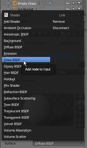
- Click Diffuse BSDF
- In the menu that appears, click Glass BSDF:
 Practical Learning: Materializing the Classic Cup
- In the Outliner, click the Restrict Rendering button on the right side of Classic Cup
- In the Outliner, click the Restrict Viewport Visibility button on the right side of Classic Cupto display it
- In the Outliner, click Classic Cup to select it
- In the Material section of the Properties window, click the New button
- Click the Preview button to expand it
- Click Diffuse BSDF
- In the menu that appears, click Glass BSDF
- In the Numeric Pad, press 0 to display the camera view
- Press N to display the Properties Region
- In the Properties Region, click the Lock Camera to View check box
- Use the mouse to center the picnic table and the other objects. Here is an example:

- In the Properties window, click the Render button

- In the Render section, click the Render button:

- On the menu bar of the UV/Image Editor, click View and click Save As Image
- Set the file name as Picnic Scene and click Save As Image
- To return to the modeling scene, press Esc
- In the Timeline, set the End to 350
- Use the mouse to zoom on, and center one, the ice vase and its ice cubes to have the objects somewhere in the front. Here is an example:

- In the Outliner, click Camera to select it
- Position the mouse in the work area, press I
- In the menu that appears, click LocRot
- In the Timeline, click the 50th frame
- Zoom in the ice vase. Here is an example:

- Position the mouse in the work area, press I, and click LocRot
- In the Timeline, click the 70th frame
- Zoom slightly away from the ice vase and turn slightly to the left. Here is an example:

- Press I and click LocRot
- In the Timeline, click the 100th frame
- Again, zoom slightly away from the ice vase and turn slightly to the left. Here is an example:

- Press I and click LocRot
- In the Timeline, click the 150th frame
- Zoom away to the left to have a left-side view of the ice vase, the champaign bucket, the bottles, and the classes. Here is an example:

- Press I and click LocRot
- In the Timeline, click the 180th frame
- Move to the left to the right to get on the back-right view. Here is an example:

- Press I and click LocRot
- In the Timeline, click the 220th frame
- Move to the back of the bottles. Here is an example:

- Press I and click LocRot
- In the Timeline, click the 250th frame
- Move to the back-left of the bottles. Here is an example:

- Press I and click LocRot
- In the Timeline, click the 280th frame
- Move to the front-right side of the cups. Here is an example:

- Press I and click LocRot
- In the Timeline, click the 350th frame
- Zoom away as much as possible. Here is an example:

- Press I and click LocRot
- In the Timeline, click the first frame
- In the Properties Region, click the Lock Camera to View check box
- Press N to close the Properties region
- In the Properties window, click the Render button

- In the Output section, click the Open button
- In the top text box, replace Ice Cubes with Picnic Scene and press Enter
- On the message box that displays, click Create New Directory
- Click the Accept button
- In the Sampling section, in the Samples section, set the Render value to 500
- In the Render section, click the Animation button
- Type Picnic Scene and press Enter
- On the message box that displays, click Create New Directory
- Click the Accept button
- In the Sampling section, in the Samples section, set the Render value to 500
- In the Render section, click the Animation button
- In the Outliner, click White Wine Bottle to select it


![]() Practical Learning: Starting the Project
Practical Learning: Starting the Project![]() Practical Learning: Creating a Classic Cup
Practical Learning: Creating a Classic Cup


![]() Practical Learning: Creating a Bottle of Red Wine
Practical Learning: Creating a Bottle of Red Wine


![]() Practical Learning: Modeling Red Wine
Practical Learning: Modeling Red Wine


![]() Practical Learning: Creating an Empty Bottle
Practical Learning: Creating an Empty Bottle![]() Practical Learning: Modeling a Bottle Cap
Practical Learning: Modeling a Bottle Cap


![]() Practical Learning: Creating a Bottle of White Wine
Practical Learning: Creating a Bottle of White Wine




![]() Practical Learning: Creating the White Wine
Practical Learning: Creating the White Wine


![]() Practical Learning: Creating an Empty Wine Glass
Practical Learning: Creating an Empty Wine Glass




![]() Practical Learning: Creating an Ice Bucket
Practical Learning: Creating an Ice Bucket


![]() Practical Learning: Creating a Champaign Bucket
Practical Learning: Creating a Champaign Bucket


![]() Practical Learning: Creating a Picnic Table
Practical Learning: Creating a Picnic Table


![]() Practical Learning: Creating Ice Cubes
Practical Learning: Creating Ice Cubes


![]() Practical Learning: Creating A Horizon
Practical Learning: Creating A Horizon![]() Practical Learning: Creating the Borders of the Eating Area
Practical Learning: Creating the Borders of the Eating Area![]() Practical Learning: Adding an Eating Area
Practical Learning: Adding an Eating Area![]() Practical Learning: Introducing Materials
Practical Learning: Introducing Materials


![]() Practical Learning: Materializing the Table Border
Practical Learning: Materializing the Table Border
![]() Practical Learning: Materializing a Champaign Bucket
Practical Learning: Materializing a Champaign Bucket
![]() Practical Learning: Materializing a Bottle of Red Wine
Practical Learning: Materializing a Bottle of Red Wine

![]() Practical Learning: Materializing an Empty Bottle
Practical Learning: Materializing an Empty Bottle![]() Practical Learning: Materializing a Bottle of White Wine
Practical Learning: Materializing a Bottle of White Wine![]() Practical Learning: Materializing the Ice Bucket
Practical Learning: Materializing the Ice Bucket![]() Practical Learning: Materializing the Horizon
Practical Learning: Materializing the Horizon![]() Practical Learning: Materializing the Eatery Border
Practical Learning: Materializing the Eatery Border![]() Practical Learning: Materializing the Eating Area
Practical Learning: Materializing the Eating Area![]() Practical Learning: Materializing the Legs of the Table
Practical Learning: Materializing the Legs of the Table![]() Practical Learning: Materializing the Ice Cubes
Practical Learning: Materializing the Ice Cubes![]() Practical Learning: Materializing the Red Wine
Practical Learning: Materializing the Red Wine![]() Practical Learning: Materializing a Bottle Cap
Practical Learning: Materializing a Bottle Cap![]() Practical Learning: Materializing the White Wine
Practical Learning: Materializing the White Wine![]() Practical Learning: Materializing an Empty Glass
Practical Learning: Materializing an Empty Glass
![]() Practical Learning: Materializing the Classic Cup
Practical Learning: Materializing the Classic Cup