
GDI Built-In Shapes
 |
GDI Built-In Shapes |
|
|
|
Multiple Polygons |
|
If you want to draw multiple polygons, you can use the PolyPolygon() function whose syntax is: BOOL PolyPolygon(HDC hdc, CONST POINT *lpPoints,
CONST INT *lpPolyCounts, int nCount);
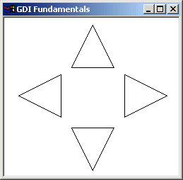
Like the Polygon() function, the lpPoints argument is an array of POINT values. The PolyPolygon() function needs to know the number of polygons you would be drawing. Each polygon uses the points of the lpPoints values but when creating the array of points, the values must be incremental. This means that PolyPolygon() will not randomly access the values of lpPoints. Each polygon has its own set of points. Unlike Polygon(), the nCount argument of PolyPolygon() is the number of polygons you want to draw and not the number of points. The lpPolyCounts argument is an array or integers. Each member of this array specifies the number of vertices (lines) that its polygon will have.. Here is an example:
|
//---------------------------------------------------------------------------
LRESULT CALLBACK WndProc(HWND hWnd, UINT Msg, WPARAM wParam, LPARAM lParam)
{
    HDC hDC;
    PAINTSTRUCT Ps;

    POINT Pt[12];
	int lpPts[] = { 3, 3, 3, 3 };

	// Top Triangle
	Pt[0].x = 125;
	Pt[0].y =  10;
	Pt[1].x = 95;
	Pt[1].y = 70;
	Pt[2].x = 155;
	Pt[2].y =  70;

	// Left Triangle
	Pt[3].x =  80;
	Pt[3].y =  80;
	Pt[4].x =  20;
	Pt[4].y = 110;
	Pt[5].x =  80;
	Pt[5].y = 140;

	// Bottom Triangle
	Pt[6].x =  95;
	Pt[6].y = 155;
	Pt[7].x = 125;
	Pt[7].y = 215;
	Pt[8].x = 155;
	Pt[8].y = 155;

	// Right Triangle
	Pt[9].x  = 170;
	Pt[9].y  =  80;
	Pt[10].x = 170;
	Pt[10].y = 140;
	Pt[11].x = 230;
	Pt[11].y = 110;

    switch(Msg)
    {
    case WM_PAINT:
        hDC = BeginPaint(hWnd, &Ps);
        PolyPolygon(hDC, Pt, lpPts, 4);
        EndPaint(hWnd, &Ps);
        break;
    case WM_DESTROY:
        PostQuitMessage(WM_QUIT);
        break;
    default:
        return DefWindowProc(hWnd, Msg, wParam, lParam);
    }
    return 0;
}
//---------------------------------------------------------------------------
|
 |
|
Rectangles and Squares |
|
A rectangle is a geometric figure made of four sides that compose four right angles. Like the line, to draw a rectangle, you must define where it starts and where it ends. This can be illustrated as follows:
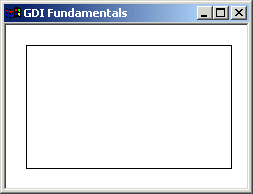
The drawing of a rectangle typically starts from a point defined as (X1, Y1) and ends at another point (X2, Y2). To draw a rectangle, you can use the Rectangle() function. Its syntax is: BOOL Rectangle(HDC hdc, int nLeftRect, int nTopRect, int nRightRect, int nBottomRect); As seen on the figure and the formula, a rectangle spans from coordinates (nLeftRect, nTopRect) to (nRightRect, nBottomRect). Here is an example:
|
//---------------------------------------------------------------------------
LRESULT CALLBACK WndProc(HWND hWnd, UINT Msg, WPARAM wParam, LPARAM lParam)
{
    HDC hDC;
    PAINTSTRUCT Ps;

    switch(Msg)
    {
    case WM_PAINT:
        hDC = BeginPaint(hWnd, &Ps);
        Rectangle(hDC, 20, 20, 226, 144);
        EndPaint(hWnd, &Ps);
        break;
    case WM_DESTROY:
        PostQuitMessage(WM_QUIT);
        break;
    default:
        return DefWindowProc(hWnd, Msg, wParam, lParam);
    }
    return 0;
}
//---------------------------------------------------------------------------
|
 |
|
When drawing a rectangle, if the value of nRightRect is less than that of nLeftRect, then the nRightRect coordinate would mark the left beginning of the figure. This scenario would also apply if the nBottomRectcoordinate were lower than nTopRect. A square is a rectangle whose sides are all equal. Therefore, to draw a square, when specifying the arguments of the Rectangle() function, make sure that |x1 - x2| = |y1 - y2|.
|
|
A Rectangle With Edges |
|
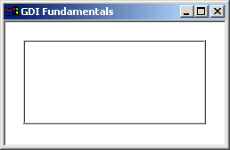
The GDI library provides another function you can use to draw a rectangle. This time you can control how the edges of the rectangle would be drawn. The function used is called DrawEdge and its syntax is: BOOL DrawEdge(HDC hdc, LPRECT qrc, UINT edge, UINT grfFlags); The qrc argument is passed as a pointer to a RECT value, which is the rectangle that would be drawn. The edge value specifies how the interior and the exterior of the edges of the rectangle would be drawn. It can be a combination of the following constants:
|
| Value | Description | |
| BDR_RAISEDINNER | The interior edge will be raised | |
| BDR_SUNKENINNER | The interior edge will be sunken | |
| BDR_RAISEDOUTER | The exterior edge will be raised | |
| BDR_SUNKENOUTER | The exterior edge will be sunken |
|
These values can be combined using the bitwise OR operator. On the other hand, you can use the following constants instead:
|
| Value | Used For | |
| EDGE_DUMP | BDR_RAISEDOUTER | BDR_SUNKENINNER | |
| EDGE_ETCHED | BDR_SUNKENOUTER | BDR_RAISEDINNER | |
| EDGE_RAISED | BDR_RAISEDOUTER | BDR_RAISEDINNER | |
| EDGE_SUNKEN | BDR_SUNKENOUTER | BDR_SUNKENINNER |
|
The grfFlags value specifies what edge(s) would be drawn. It can have one of the following values:
|
| Value | Description | |
| BF_RECT | The entire rectangle will be drawn | |
| BF_TOP | Only the top side will be drawn | |
| BF_LEFT | Only the left side will be drawn | |
| BF_BOTTOM | Only the bottom side will be drawn | |
| BF_RIGHT | Only the right side will be drawn | |
| BF_TOPLEFT | Both the top and the left sides will be drawn | |
| BF_BOTTOMLEFT | Both the bottom and the left sides will be drawn | |
| BF_TOPRIGHT | Both the top and the right sides will be drawn | |
| BF_BOTTOMRIGHT | Both the bottom and the right sides will be drawn | |
| BF_DIAGONAL_ENDBOTTOMLEFT | A diagonal line will be drawn from the top-right to the bottom-left corners | |
| BF_DIAGONAL_ENDBOTTOMRIGHT | A diagonal line will be drawn from the top-left to the bottom-right corners | |
| BF_DIAGONAL_ENDTOPLEFT | A diagonal line will be drawn from the bottom-right to the top-left corners | |
| BF_DIAGONAL_ENDTOPRIGHT | A diagonal line will be drawn from the bottom-left to the top-right corners |
Here is an example:
//---------------------------------------------------------------------------
LRESULT CALLBACK WndProc(HWND hWnd, UINT Msg, WPARAM wParam, LPARAM lParam)
{
    HDC hDC;
    PAINTSTRUCT Ps;

    RECT Recto = {20, 20, 225, 115};

    switch(Msg)
    {
    case WM_PAINT:
        hDC = BeginPaint(hWnd, &Ps);
	DrawEdge(hDC, &Recto, BDR_RAISEDOUTER | BDR_SUNKENINNER, BF_RECT);
        EndPaint(hWnd, &Ps);
        break;
    case WM_DESTROY:
        PostQuitMessage(WM_QUIT);
        break;
    default:
        return DefWindowProc(hWnd, Msg, wParam, lParam);
    }
    return 0;
}
//---------------------------------------------------------------------------
|
 |
|
Ellipses and Circles |
|
An ellipse is a closed continuous line whose points are positioned so that two points exactly opposite each other have the exact same distant from a central point. It can be illustrated as follows:
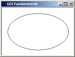
Because an ellipse can fit in a rectangle, in GDI programming, an ellipse is defined with regards to a rectangle it would fit in. Therefore, to draw an ellipse, you specify its rectangular corners. The syntax used to do this is: BOOL Ellipse(HDC hdc, int nLeftRect, int nTopRect, int nRightRect, int nBottomRect); The arguments of this function play the same roll as those of the Rectangle() function:
Here is an example:
|
//---------------------------------------------------------------------------
LRESULT CALLBACK WndProc(HWND hWnd, UINT Msg, WPARAM wParam, LPARAM lParam)
{
    HDC hDC;
    PAINTSTRUCT Ps;

    switch(Msg)
    {
    case WM_PAINT:
        hDC = BeginPaint(hWnd, &Ps);
		Ellipse(hDC, 20, 20, 226, 144);
        EndPaint(hWnd, &Ps);
        break;
    case WM_DESTROY:
        PostQuitMessage(WM_QUIT);
        break;
    default:
        return DefWindowProc(hWnd, Msg, wParam, lParam);
    }
    return 0;
}
//---------------------------------------------------------------------------
|
 |
|
Round Rectangles and Round Squares |
|
A rectangle qualifies as round if its corners do not form straight angles but rounded corners. It can be illustrated as follows:
To draw such a rectangle, you can use the RoundRect() function. Its syntax is: BOOL RoundRect(HDC hdc,
int nLeftRect, int nTopRect, int nRightRect, int nBottomRect,
int nWidth, int nHeight );
When this member function executes, the rectangle is drawn from the (nLeftRect, nTopRect) to the (nRightRect, nBottomRect) points. The corners are rounded by an ellipse whose width would be nWidth and the ellipse's height would be nHeight. Here is an example:
|
//---------------------------------------------------------------------------
LRESULT CALLBACK WndProc(HWND hWnd, UINT Msg, WPARAM wParam, LPARAM lParam)
{
    HDC hDC;
    PAINTSTRUCT Ps;

    switch(Msg)
    {
    case WM_PAINT:
        hDC = BeginPaint(hWnd, &Ps);
	RoundRect(hDC, 20, 20, 275, 188, 42, 38);
        EndPaint(hWnd, &Ps);
        break;
    case WM_DESTROY:
        PostQuitMessage(WM_QUIT);
        break;
    default:
        return DefWindowProc(hWnd, Msg, wParam, lParam);
    }
    return 0;
}
//---------------------------------------------------------------------------
|
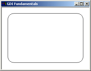 |
A round square is a square whose corners are rounded.
|
Pies |
|
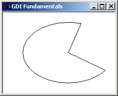
A pie is a fraction of an ellipse delimited by two lines that span from the center of the ellipse to one side each. It can be illustrated as follows:
To draw a pie, you can use the Pie() function whose syntax is: BOOL Pie(HDC hdc,
int nLeftRect, int nTopRect, int nRightRect, int nBottomRect,
int nXRadial1, int nYRadial1, int nXRadial2, int nYRadial2);
The (nLeftRect, nTopRect) point determines the upper-left corner of the rectangle in which the ellipse that represents the pie fits. The (nRightRect, nBottomRect) point is the bottom-right corner of the rectangle. The (nXRadial1, nYRadial1) point species the end point of the pie. To complete the pie, a line is drawn from (nXRadial1, nYRadial1) to the center and from the center to the (nXRadial2, nYRadial2) points. Here is an example:
|
//---------------------------------------------------------------------------
LRESULT CALLBACK WndProc(HWND hWnd, UINT Msg, WPARAM wParam, LPARAM lParam)
{
    HDC hDC;
    PAINTSTRUCT Ps;

    switch(Msg)
    {
    case WM_PAINT:
        hDC = BeginPaint(hWnd, &Ps);
	Pie(hDC, 40, 20, 226, 144, 155, 32, 202, 115);
        EndPaint(hWnd, &Ps);
        break;
    case WM_DESTROY:
        PostQuitMessage(WM_QUIT);
        break;
    default:
        return DefWindowProc(hWnd, Msg, wParam, lParam);
    }
    return 0;
}
//---------------------------------------------------------------------------
|
 |
|
Arcs |
|
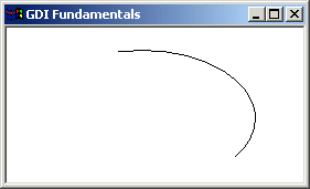
An arc is a portion or segment of an ellipse, meaning an arc is a non-complete ellipse. Because an arc must confirm to the shape of an ellipse, it is defined as it fits in a rectangle and can be illustrated as follows:
To draw an arc, you can use the Arc() function whose syntax is: BOOL Arc(HDC hdc,
int nLeftRect, int nTopRect, int nRightRect, int nBottomRect,
int nXStartArc, int nYStartArc, int nXEndArc, int nYEndArc);
Besides the left (nLeftRect, nTopRect) and the right (nRightRect, nBottomRect) borders of the rectangle in which the arc would fit, an arc must specify where it starts and where it ends. These additional points are set as the (nXStartArc, nYStartArc) and (nXEndArc, nYEndArc) points of the figure. Based on this, the above arc can be illustrated as follows:
Here is an example:
|
//---------------------------------------------------------------------------
LRESULT CALLBACK WndProc(HWND hWnd, UINT Msg, WPARAM wParam, LPARAM lParam)
{
    HDC hDC;
    PAINTSTRUCT Ps;

    switch(Msg)
    {
    case WM_PAINT:
        hDC = BeginPaint(hWnd, &Ps);
	Arc(hDC, 20, 20, 226, 144, 202, 115, 105, 32);
        EndPaint(hWnd, &Ps);
        break;
    case WM_DESTROY:
        PostQuitMessage(WM_QUIT);
        break;
    default:
        return DefWindowProc(hWnd, Msg, wParam, lParam);
    }
    return 0;
}
//---------------------------------------------------------------------------
|
 |
|
Besides the Arc() function, the GDI library provides the ArcTo() member function used to draw an arc. Its syntaxes is: BOOL ArcTo(HDC hdc,
int nLeftRect, int nTopRect, int nRightRect, int nBottomRect,
int nXRadial1, int nYRadial1, int nXRadial2, int nYRadial2);
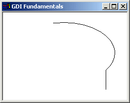
This function uses the same arguments as Arc(). The difference is that while Arc() starts drawing at (nXRadial1, nYRadial1), ArcTo() does not inherently control the drawing starting point. It refers to the current point, exactly like the LineTo() (and the PolylineTo()) function. Therefore, if you want to specify where the drawing should start, can call MoveToEx() before ArcTo(). Here is an example: |
//---------------------------------------------------------------------------
LRESULT CALLBACK WndProc(HWND hWnd, UINT Msg, WPARAM wParam, LPARAM lParam)
{
    HDC hDC;
    PAINTSTRUCT Ps;

    switch(Msg)
    {
    case WM_PAINT:
        hDC = BeginPaint(hWnd, &Ps);
	MoveToEx(hDC, 207, 155, NULL);
	ArcTo(hDC, 20,  20, 226, 144, 202, 115, 105,  32);
        EndPaint(hWnd, &Ps);
        break;
    case WM_DESTROY:
        PostQuitMessage(WM_QUIT);
        break;
    default:
        return DefWindowProc(hWnd, Msg, wParam, lParam);
    }
    return 0;
}
//---------------------------------------------------------------------------
|
 |
|
The Arc's Direction |
Here is and arc we drew earlier with a call to Arc():
//---------------------------------------------------------------------------
LRESULT CALLBACK WndProc(HWND hWnd, UINT Msg, WPARAM wParam, LPARAM lParam)
{
    HDC hDC;
    PAINTSTRUCT Ps;

    switch(Msg)
    {
    case WM_PAINT:
        hDC = BeginPaint(hWnd, &Ps);
	Arc(hDC, 20, 20, 226, 144, 202, 115, 105, 32);
        EndPaint(hWnd, &Ps);
        break;
    case WM_DESTROY:
        PostQuitMessage(WM_QUIT);
        break;
    default:
        return DefWindowProc(hWnd, Msg, wParam, lParam);
    }
    return 0;
}
//---------------------------------------------------------------------------
|
 |
|
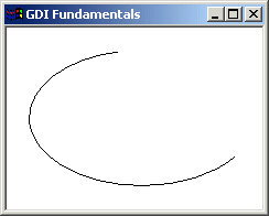
You may wonder why the arc is drawn to the right side of a vertical line that would cross the center of the ellipse instead of the left. This is because the drawing of an arc is performed from right to left or from bottom to top, in the opposite direction of the clock. This is known as the counterclockwise direction. To control this orientation, the GDI library is equipped with the SetArcDirection() function. Its syntax is: int SetArcDirection(HDC hdc, int ArcDirection); This function specifies the direction the Arc() function should follow from the starting to the end points. The argument passed as ArcDirection controls this orientation. It can have the following values:
|
| Value | Orientation | |
| AD_CLOCKWISE | The figure is drawn clockwise | |
| AD_COUNTERCLOCKWISE | The figure is drawn counterclockwise |
|
The default value of the direction is AD_COUNTERCLOCKWISE. Therefore, this would be used if you do not specify a direction. Here is an example that uses the same values as above with a different orientation:
|
//---------------------------------------------------------------------------
LRESULT CALLBACK WndProc(HWND hWnd, UINT Msg, WPARAM wParam, LPARAM lParam)
{
    HDC hDC;
    PAINTSTRUCT Ps;

    switch(Msg)
    {
    case WM_PAINT:
        hDC = BeginPaint(hWnd, &Ps);
        SetArcDirection(hDC, AD_CLOCKWISE);
        Arc(hDC, 20, 20, 226, 144, 202, 115, 105, 32);
        EndPaint(hWnd, &Ps);
        break;
    case WM_DESTROY:
        PostQuitMessage(WM_QUIT);
        break;
    default:
        return DefWindowProc(hWnd, Msg, wParam, lParam);
    }
    return 0;
}
//---------------------------------------------------------------------------
|
 |
|
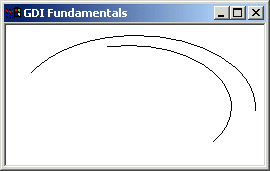
After calling SetArcDirection() and changing the previous direction, all drawings would use the new direction to draw arcs using Arc() or ArcTo() and other figures (such as chords, ellipses, pies, and rectangles). Here is an example:
|
//---------------------------------------------------------------------------
LRESULT CALLBACK WndProc(HWND hWnd, UINT Msg, WPARAM wParam, LPARAM lParam)
{
    HDC hDC;
    PAINTSTRUCT Ps;

    switch(Msg)
    {
    case WM_PAINT:
        hDC = BeginPaint(hWnd, &Ps);
        SetArcDirection(hDC, AD_COUNTERCLOCKWISE);
        Arc(hDC, 20, 20, 226, 144, 202, 115, 105, 32);
        Arc(hDC, 10, 10, 250, 155, 240, 85, 24, 48);
        EndPaint(hWnd, &Ps);
        break;
    case WM_DESTROY:
        PostQuitMessage(WM_QUIT);
        break;
    default:
        return DefWindowProc(hWnd, Msg, wParam, lParam);
    }
    return 0;
}
//---------------------------------------------------------------------------
|
 |
|
If you want to change the direction, you must call SetArcDirection() with the desired value. Here is an example;
|
//---------------------------------------------------------------------------
LRESULT CALLBACK WndProc(HWND hWnd, UINT Msg, WPARAM wParam, LPARAM lParam)
{
    HDC hDC;
    PAINTSTRUCT Ps;

    switch(Msg)
    {
    case WM_PAINT:
        hDC = BeginPaint(hWnd, &Ps);
        SetArcDirection(hDC, AD_COUNTERCLOCKWISE);
        Arc(hDC, 20, 20, 226, 144, 202, 115, 105, 32);
        SetArcDirection(hDC, AD_CLOCKWISE);
        Arc(hDC, 10, 10, 250, 155, 240, 85, 24, 48);
        EndPaint(hWnd, &Ps);
        break;
    case WM_DESTROY:
        PostQuitMessage(WM_QUIT);
        break;
    default:
        return DefWindowProc(hWnd, Msg, wParam, lParam);
    }
    return 0;
}
//---------------------------------------------------------------------------
|
 |
|
At any time, you can find out the current direction used. This is done by calling the GetArcDirection() function. Its syntax is: int GetArcDirection(HDC hdc); This function returns the current arc direction as AD_CLOCKWISE or AD_COUNTERCLOCKWISE.
|
|
Angular Arcs |
|
You can (also) draw an arc using the AngleArc() function. Its syntax is: BOOL AngleArc(HDC hdc, int X, int Y, DWORD dwRadius,
FLOAT eStartAngle, FLOAT eSweepAngle);
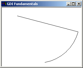
This function draws a line and an arc connected. The arc is based on a circle and not an ellipse. This implies that the arc fits inside a square and not a rectangle. The circle that would be the base of the arc is defined by its center located at C(X, Y) with a radius of dwRadius. The arc starts at an angle of eStartAngle. The angle is based on the x axis and must be positive. That is, it must range from 0° to 360°. If you want to specify an angle that is below the x axis, such as -15°, use 360º-15°=345°. The last argument, eSweepAngle, is the angular area covered by the arc. The AngleArc() function does not control where it starts drawing. This means that it starts at the origin, unless a previous call to MoveToEx() specified the beginning of the drawing. Here is an example:
|
//---------------------------------------------------------------------------
LRESULT CALLBACK WndProc(HWND hWnd, UINT Msg, WPARAM wParam, LPARAM lParam)
{
    HDC hDC;
    PAINTSTRUCT Ps;

    switch(Msg)
    {
    case WM_PAINT:
        hDC = BeginPaint(hWnd, &Ps);
        MoveToEx(hDC, 52, 28, NULL);
        AngleArc(hDC, 120, 45, 142, 345, -65);
        EndPaint(hWnd, &Ps);
        break;
    case WM_DESTROY:
        PostQuitMessage(WM_QUIT);
        break;
    default:
        return DefWindowProc(hWnd, Msg, wParam, lParam);
    }
    return 0;
}
//---------------------------------------------------------------------------
|
 |
|
Chords |
|
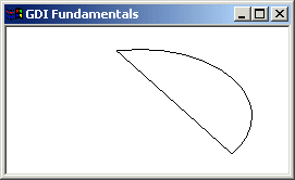
The arcs we have drawn so far are considered open figures because they are made of a line that has a beginning and an end (unlike a circle or a rectangle that do not). A chord is an arc whose two ends are connected by a straight line. In other words, a chord is an ellipse that is divided by a straight line from one side to another:
To draw a chord, you can use the Chord() function. Its syntax is as follows: BOOL Chord(HDC hdc,
int nLeftRect, int nTopRect, int nRightRect, int nBottomRect,
int nXRadial1, int nYRadial1, int nXRadial2, int nYRadial2);
The nLeftRect, nTopRect, nRightRect, and nBottomRect are the coordinates of the rectangle in which the chord of the circle would fit. These nXRadial1 and nYRadial1 coordinates specify where the arc that holds the chord starts. To complete the chord, a line is drawn from (nXRadial1, nYRadial1) to (nXRadial2, nYRadial2 ). Here is an example:
|
//---------------------------------------------------------------------------
LRESULT CALLBACK WndProc(HWND hWnd, UINT Msg, WPARAM wParam, LPARAM lParam)
{
    HDC hDC;
    PAINTSTRUCT Ps;

    switch(Msg)
    {
    case WM_PAINT:
        hDC = BeginPaint(hWnd, &Ps);
        Chord(hDC, 20, 20, 226, 144, 202, 115, 105, 32);
        EndPaint(hWnd, &Ps);
        break;
    case WM_DESTROY:
        PostQuitMessage(WM_QUIT);
        break;
    default:
        return DefWindowProc(hWnd, Msg, wParam, lParam);
    }
    return 0;
}
|
 |
|
Bézier Curves |
|
A bézier line is an arc that is strictly based on a set number of points instead of on an ellipse. A bézier curve uses at least four points to draw on. A bézier line with four points can be illustrated as follows:
To draw this line (with four points), the compiler would draw a curve from the first to the fourth points. Then it would bend the curve by bringing each middle (half-center) side close to the second and the third points respectively, of course without touching those second and third points. For example, the above bézier curve could have been drawn using the following four points:
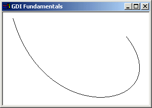
PolyBezier(): To draw a bézier curve, the GDI library provides the PolyBezier() function. Its syntax is: BOOL PolyBezier(HDC hdc, CONST POINT *lppt, DWORD cPoints); The lppt argument is an array of POINT values. The cPoints argument specifies the number of points that will be used to draw the line. Here is an example:
|
//---------------------------------------------------------------------------
LRESULT CALLBACK WndProc(HWND hWnd, UINT Msg, WPARAM wParam, LPARAM lParam)
{
    HDC hDC;
    PAINTSTRUCT Ps;

    POINT Pt[4] = { {  20,  12 }, {  88, 246 }, { 364, 192 }, { 250,  48 } };

    switch(Msg)
    {
    case WM_PAINT:
        hDC = BeginPaint(hWnd, &Ps);
        PolyBezier(hDC, Pt, 4);
        EndPaint(hWnd, &Ps);
        break;
    case WM_DESTROY:
        PostQuitMessage(WM_QUIT);
        break;
    default:
        return DefWindowProc(hWnd, Msg, wParam, lParam);
    }
    return 0;
}
//---------------------------------------------------------------------------
|
 |
|
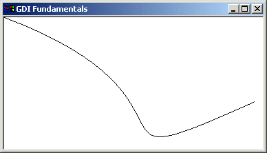
PolyBezierTo(): The PolyBezier() function requires at least four points to draw its curve. This is because it needs to know where to start drawing. Another way you can control where the curve would start is by using the PolyBezierTo() function. Its syntax is: BOOL PolyBezierTo(HDC hdc, CONST POINT *lppt, DWORD cCount); The PolyBezierTo() function draws a bézier curve. Its first argument is a pointer to an array of POINT values. This member function requires at least three points. It starts drawing from the current line to the third point. If you do not specify the current line, it would consider the origin (0, 0). The first and the second lines are used to control the curve. The cCount argument is the number of points that would be considered. Here is an example:
|
//---------------------------------------------------------------------------
LRESULT CALLBACK WndProc(HWND hWnd, UINT Msg, WPARAM wParam, LPARAM lParam)
{
    HDC hDC;
    PAINTSTRUCT Ps;

    POINT Pt[4] = { {  320, 120 }, {  88, 246 }, { 364, 122 } };

    switch(Msg)
    {
    case WM_PAINT:
        hDC = BeginPaint(hWnd, &Ps);
        PolyBezierTo(hDC, Pt, 3);
        EndPaint(hWnd, &Ps);
        break;
    case WM_DESTROY:
        PostQuitMessage(WM_QUIT);
        break;
    default:
        return DefWindowProc(hWnd, Msg, wParam, lParam);
    }
    return 0;
}
//---------------------------------------------------------------------------
|
 |
|
|
||
| Previous | Copyright © 2004-2010 FunctionX, Inc. | Next |
|
|
||