Modeling Simple Door Locks
Modeling Simple Door Locks
Creating a First Lock
![]() Practical Learning: Modeling a First Lock
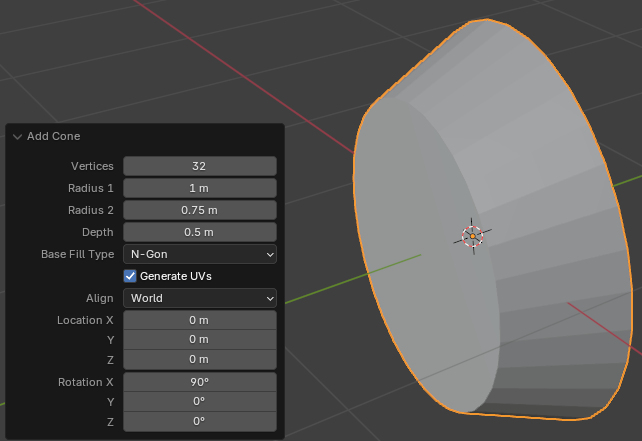
Practical Learning: Modeling a First Lock
Radius 2: 0.75
Depth:    0.5
Align:    View
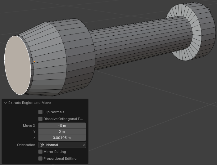
Move Z: 0.45
Move Z: 0.1
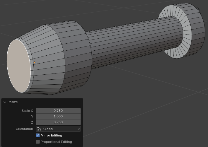
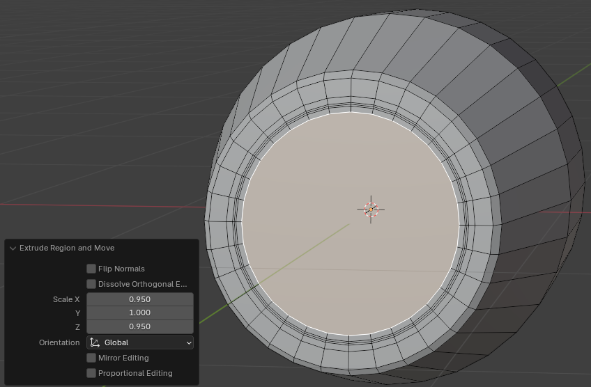
Scale: X: 0.95
Z: 0.95Scale: X: 0.5
Y: 0.5
Z: 0.5
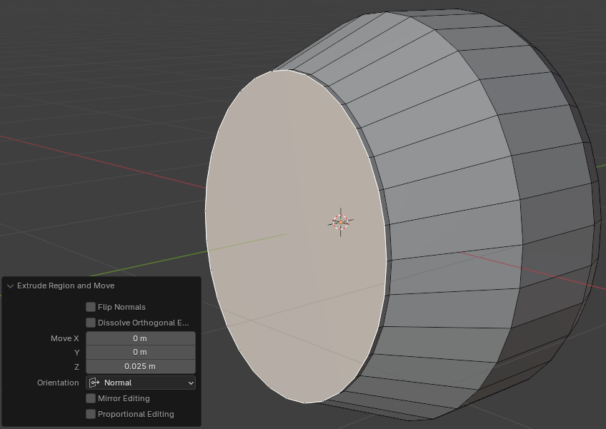
Move Z: 0.025
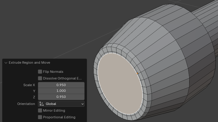
Scale: X: 0.95
       Z: 0.95

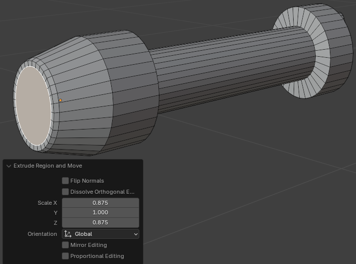
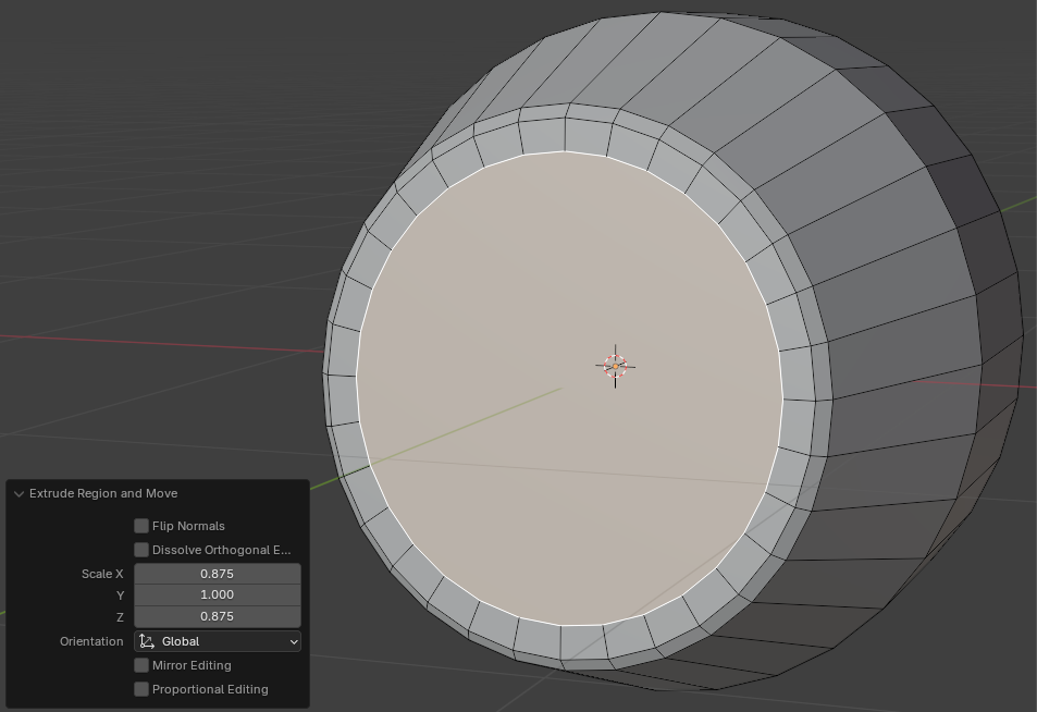
Scale: X: 0.875
       Z: 0.875
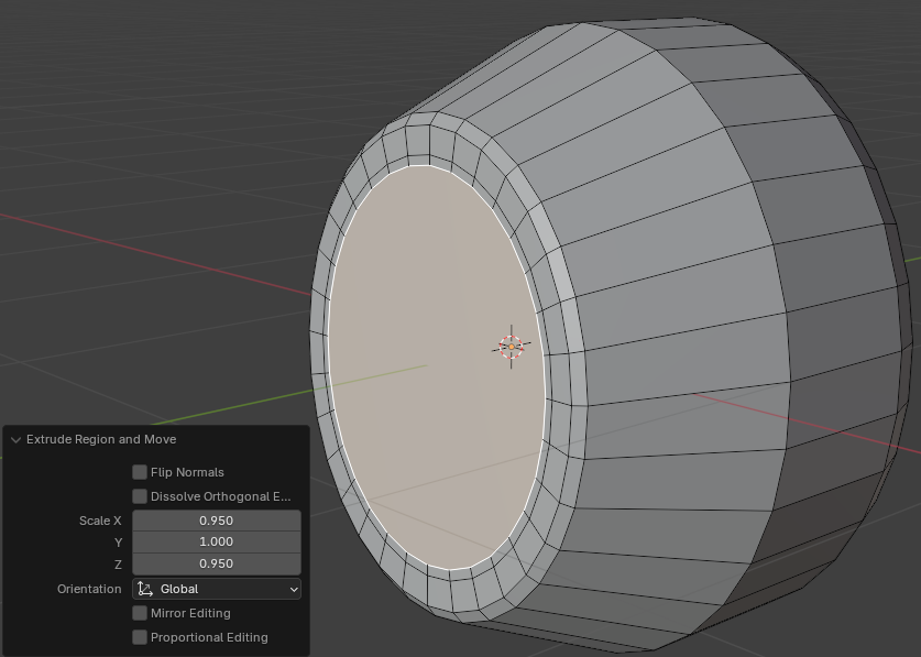
Scale X: 0.95
       Z: 0.95
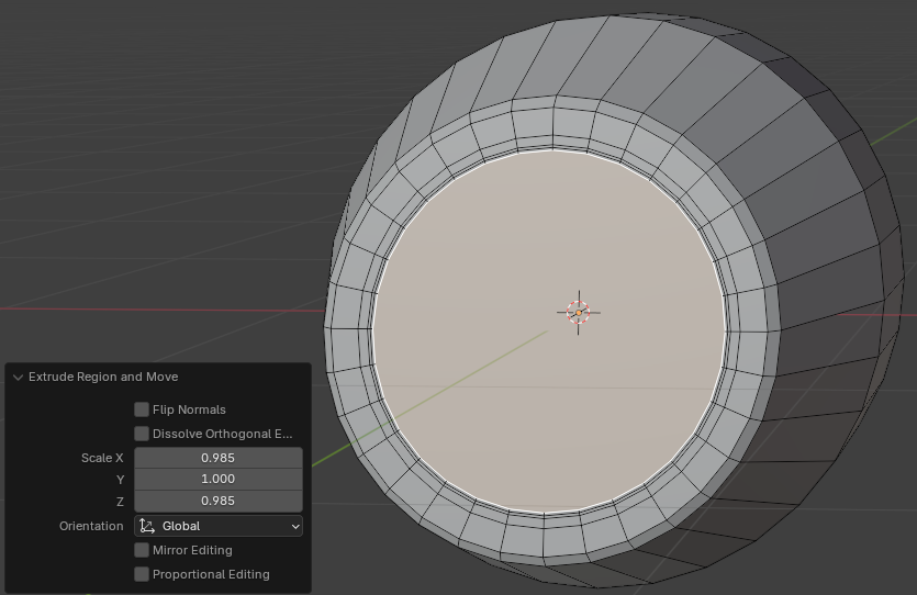
Scale: X: 0.985
       Z: 0.985
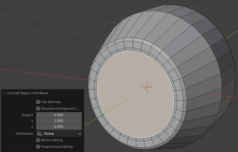
Scale: X: 0.985
       Z: 0.985
Scale: X: 0.95
       Z: 0.95
Move: X: 0
      Y: 0.25
      Z: 0


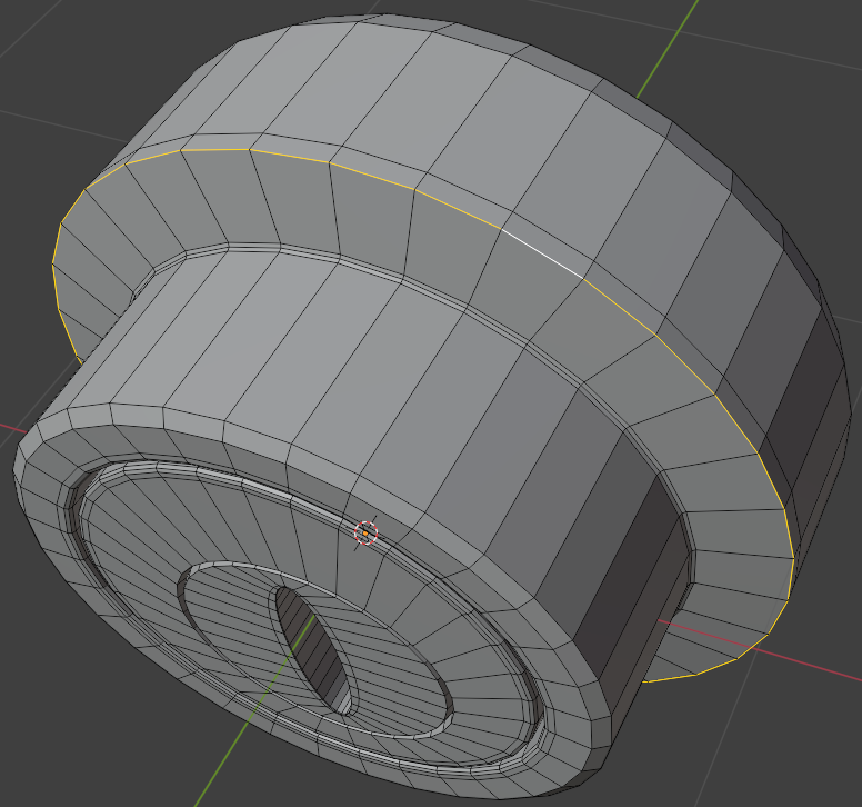
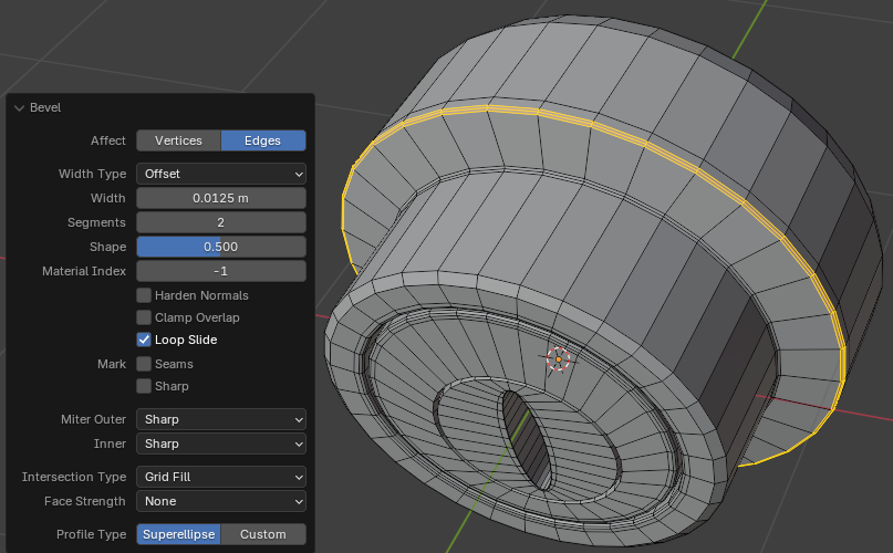
Width:    0.0125
Segments: 2


Width:    0.0125
Segments: 2

Scale X: 0.65
      Z: 0.65

Move X: 0
          Y: 0
          Z: -0.105

Move X: 0.975
Z: 0.975Move X: 0.975
Z: 0.975Move X: 0.205
Z: 0.85


Move: X: 0
       Y: 0.025
       Z: 0


Move X:  0
     Y:  0
     Z: -0.75


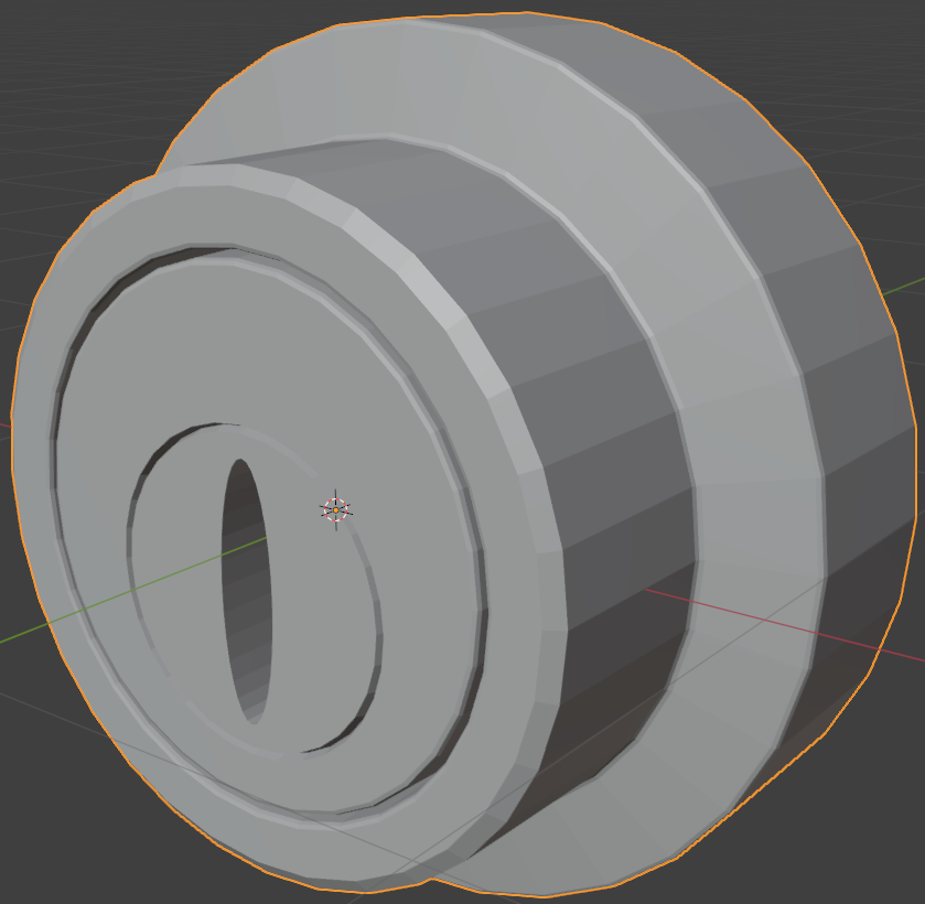
Levels Viewport: 2

Creating a Varying Lock
.
![]() Practical Learning: Creating a Varying Lock
Practical Learning: Creating a Varying Lock
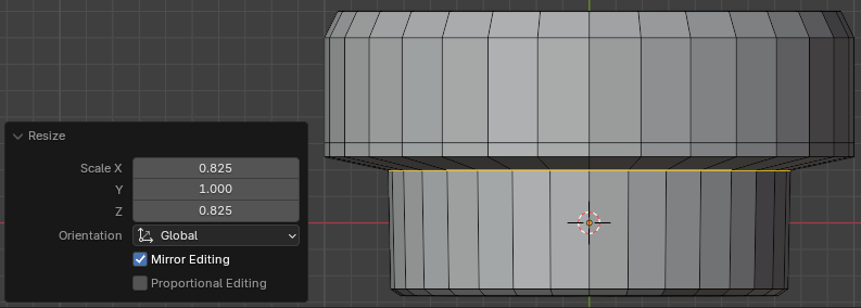
Scale X: 0.825
      Z: 0.825
Width:    0.0125
Segments: 2
Width:    0.0125
Segments: 2
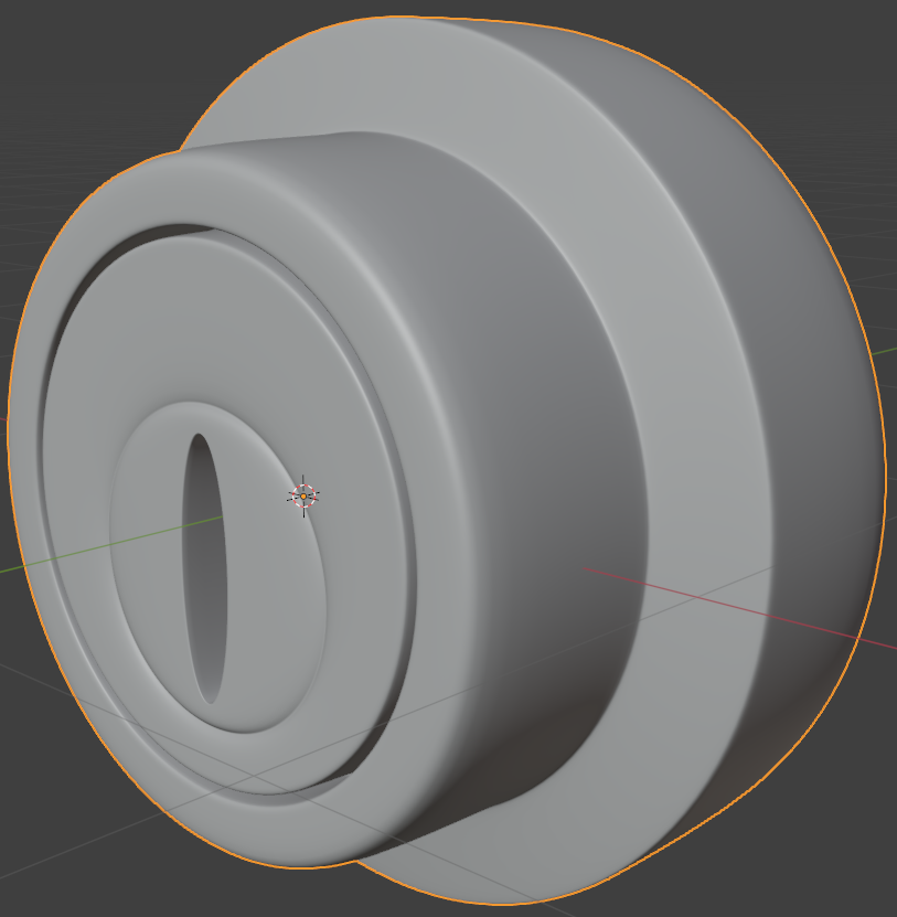
Levels Viewport: 2
|
|
|||
| Previous | Copyright © 2016-2024, FunctionX | Monday 26 August 2024, 12:30 | Next |
|
|
|||