Modeling the Lock Base
A door handle is used on a door lock to allow a person to unlock the lock and open the door. Doors use various types of handles. In this exercise, we will model a simple door handle. We will first model the base of the door lock.
 Practical Learning: Modeling the Lock Base
- Start Blender
- Click the default cube to select it (it should be selected already)
- On your keyboard, press Delete to remove that cube
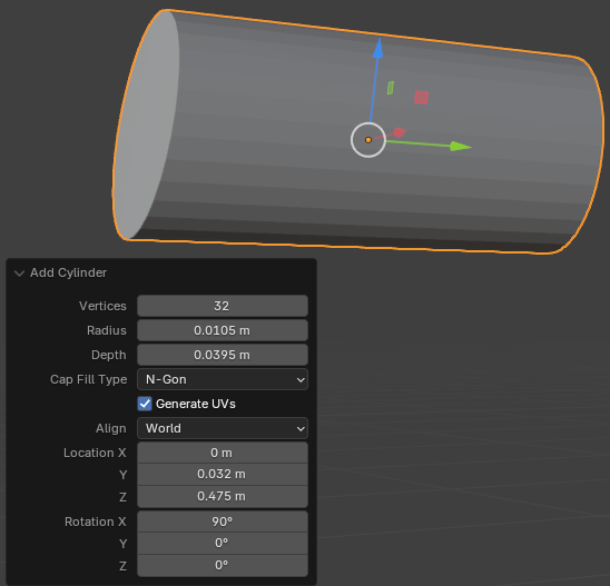
- On the top menu bar, click Add -> Mesh -> Cylinder
- In the bottom-left section of the 3D Viewport, click Add Cylinder to expand its window
- In the Add Cylinder window, change the following characteristics:
Radius:     0.0105
Depth:      0.0395
Location X: 0
         Y: 0.032
         Z: 0.475
Rotation X: 90
- In the Object section of the Properties window, click Cone to select the name
- Type Door-Handle-Base as the name and press Enter
- To edit the door handle base, on the top-main menu of Blender, click Modeling
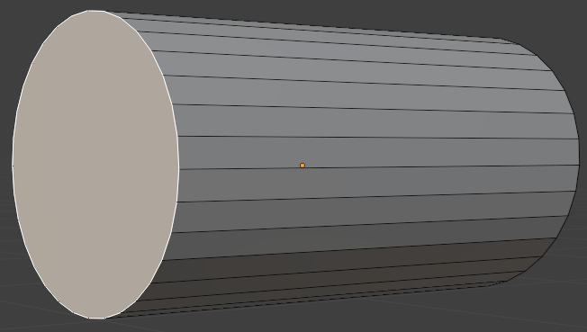
- Click and drag the Rotate button to see the front or the back face of the cylinder
- On the top menu, click the Face button

- Click a large vertical face to select it
- Click and drag the Rotate button to see the other face of the cylinder
- Press and hold Shift
- Click the other face to select it
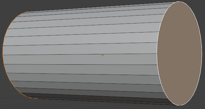
- Release Shift
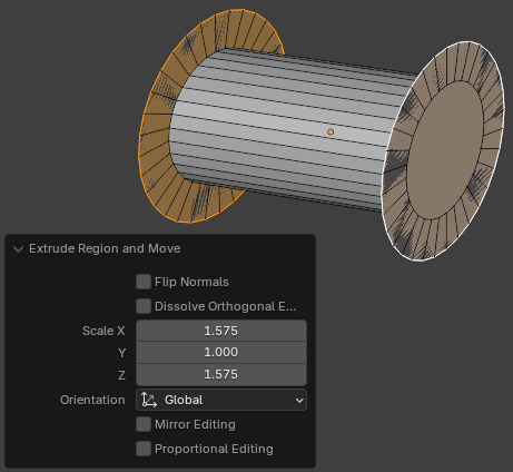
- Press E to extrude
- Press S to resize, and press Enter
- In the Extrude Region and Move window, change the X and Z values as follows:
Scale X: 1.575
      Z: 1.575
- Position the mouse in the 3D Viewport and press Alt + E
- In the menu that appears, click Extrude Faces Along Normals
- Move the mouse slightly away from the object and click
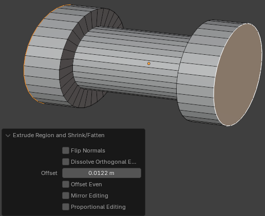
- In the Extrude Region and Shrink/Fatten window, change the Offset value to 0.0025:
Offset: 0.01225
- On the left toolbar, click and hold the mouse on the Extrude Region button:
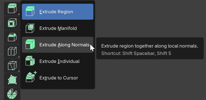
- In the menu that appears, click Extrude Along Normals
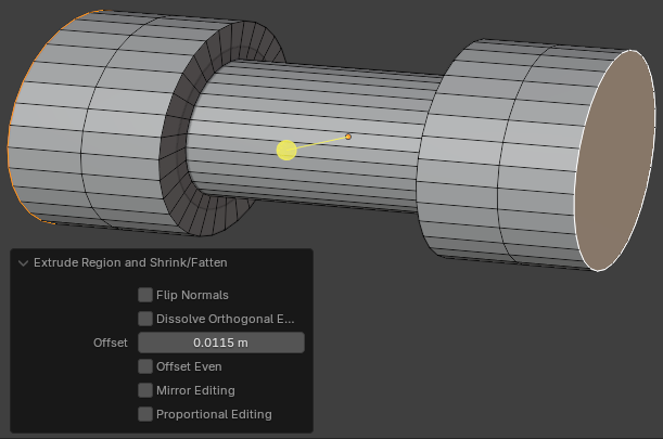
- On the object, drag the yellow button slightly away from the object and release the mouse
- In the Extrude Region and Shrink/Fatten window, change the Offset value to 0.0115
Offset: 0.0115
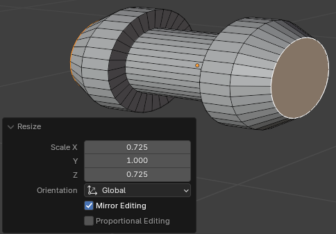
- On the left toolbar, click the Select Box button

- Press S to resize the faces and press Enter
- In the Resize window, change the X and Z values as follows:
Scale X: 0.725
      Z: 0.725
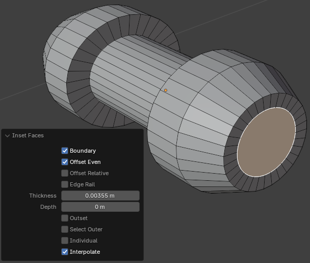
- Press I to create insets and press Enter
- In the Inset Faces window, change the Thickness value to 0.00355:
Thickness: 0.00355
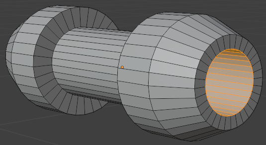
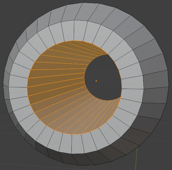
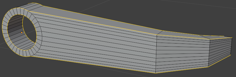
- While both faces are still selected, on the top menu, click Edge -> Bridge Edge Loops:
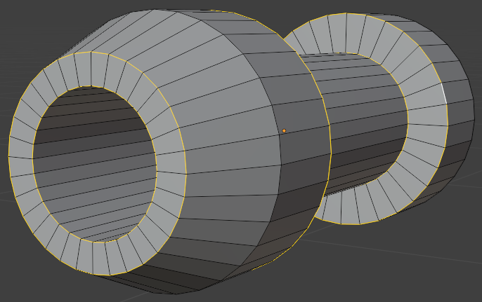
- On the top menu, click the Edge button

- Press and hold Alt
- Click one of the hard edges of the object
- Press and hold Shift to make sure you are holding Shift and Alt
- Click each of the other sharp borders of the object
- Release Shift and Alt:
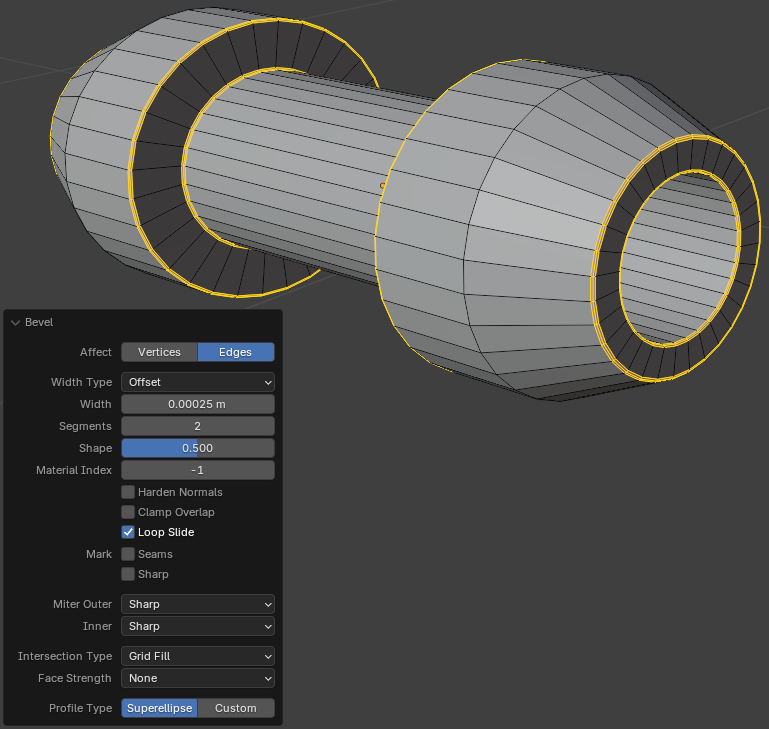
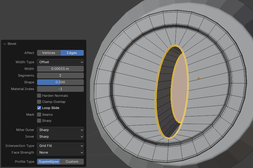
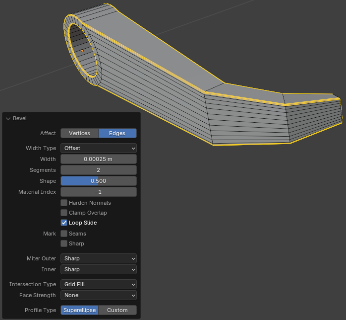
- To create bevels, press Ctrl + B, and press Enter
- In the Bevel window, change the values as follows:
Width:    0.00025
Segments: 2
- On the top-main menu of Blender, click Layout
Modeling a Door Cylinder
A door lock usually has a cylindrical where a person can insert a key and tuen that key to open the door. We will model such a cylinder in this section.
Practical Learning: Modeling a Door Cylinder
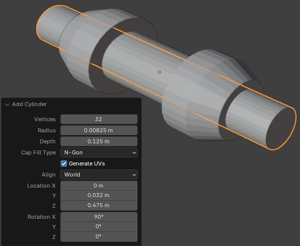
- To add an object, press Shift + A -> Add -> Cylinder
- In the Add Cylinder window, change the following values:
Radius:  0.00825
Depth:   0.125
Location X: 0
         Y: 0.032
         Z: 0.475
Rotation X:  90
- To edit the cylinder, on the top-main menu of Blender, click Modeling
- On the top menu, click the Face button
- Click a large vertical face to select it
- Click and drag the Rotate button to see the other face of the cylinder
- Press and hold Shift
- Click the other face to select it
- Release Shift
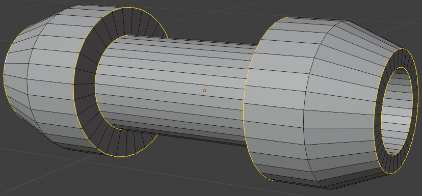
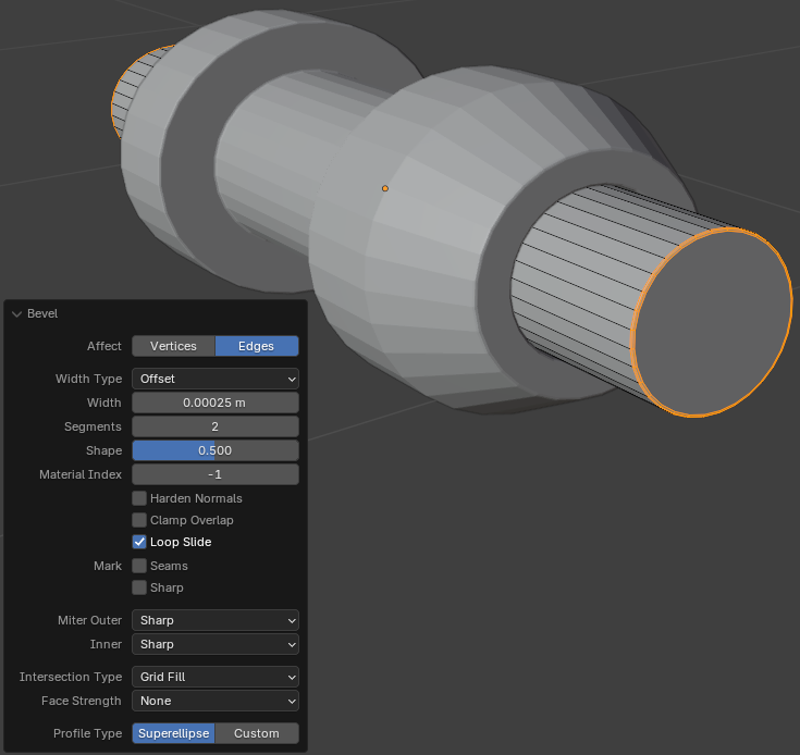
- To create bevels, press Ctrl + B, and press Enter
- In the Bevel window, change the values as follows:
Width:    0.00025
Segments: 2
- Click and drag the Rotate button so you can see the back face
- Click the large vertical face
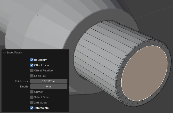
- Press I to create an inset and press Enter
- In the Inset Faces window, change the values as follows:
Thickness: 0.00125
Depth:     0
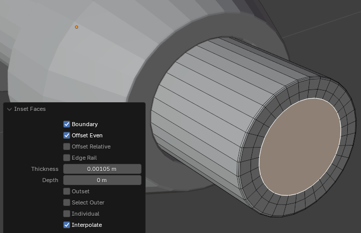
- Position the mouse in the 3D Viewport. Press I to create an inset and press Enter
- In the Inset Faces window, change the values as follows:
Thickness: 0.00105
Depth:     0
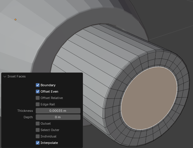
- Position the mouse in the 3D Viewport. Press I to create an inset and press Enter
- In the Inset Faces window, change the values as follows:
Thickness: 0.00035
Depth:     0
- Position the mouse in the 3D Viewport. Press G to movee the face and press Enter
- In the Move window, change the values as follows:
Move X: 0
     Y: 0.00025
     Z: 0
- Position the mouse in the 3D Viewport. Press E to extrude the face, then press S to resize, and press Enter
- In the Extrude Region and Move window, change the scale values as follows:
Move X: 0.985
     Z: 0.985
- Position the mouse in the 3D Viewport. Press E to extrude the face, then press S to resize, and press Enter
- In the Extrude Region and Move window, change the scale values as follows:
Move X: 0.325
     Z: 0.875
- Position the mouse in the 3D Viewport. Press I to create an inset and press Enter
- In the Inset Faces window, set the Thickness value to follows:
Thickness: 0.00015
Depth:     0
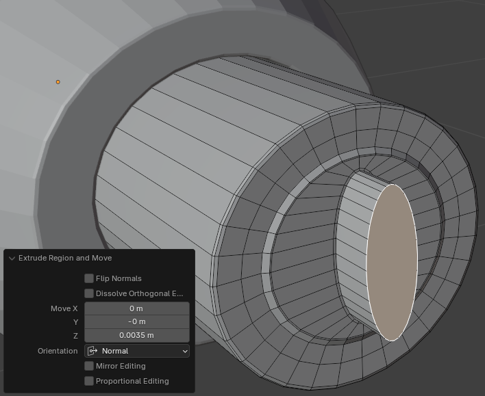
- Position the mouse in the 3D Viewport. Press E to extrude and press Enter
- In the Extrude Region and Move window, set the Move values as follows:
Move X: 0
     Y: 0
     Z: 0.0035
- Position the mouse in the 3D Viewport. Press I to create an inset and press Enter
- In the Inset Faces window, set the Thickness value to follows:
Thickness: 0.00015
Depth:     0
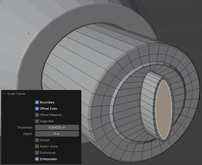
- Position the mouse in the 3D Viewport. Press I to create an inset and press Enter
- In the Inset Faces window, change the values as follows:
Thickness: 0.00025
Depth:     0
- Click and drag the Rotate button so you can see the front face
- Click the large vertical face
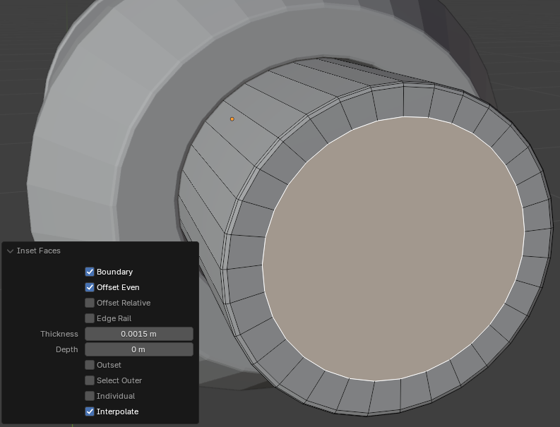
- Position the mouse in the 3D Viewport. Press I to create an inset and press Enter
- In the Inset Faces window, change the values as follows:
Thickness: 0.0015
Depth:     0
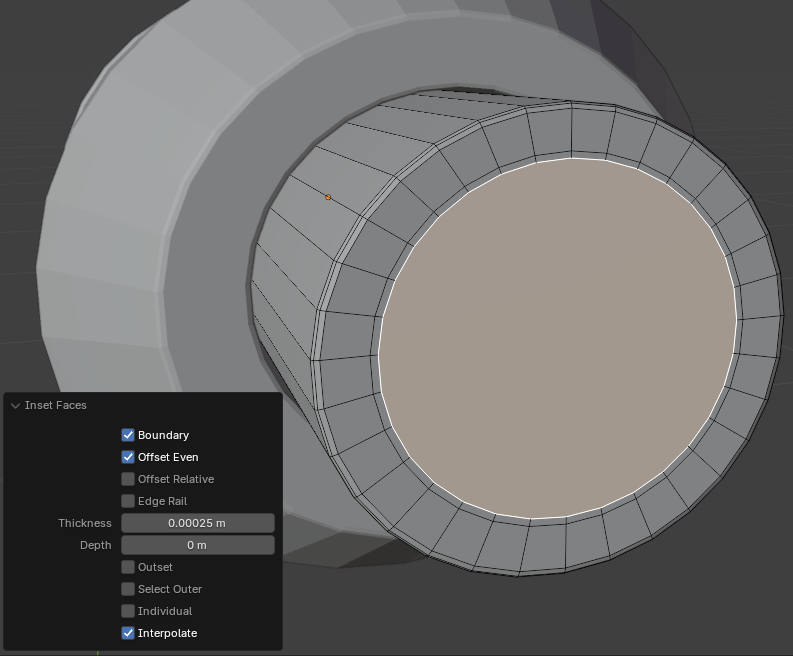
- Position the mouse in the 3D Viewport. Press I to create an inset and press Enter
- In the Inset Faces window, change the values as follows:
Thickness: 0.00025
Depth:     0
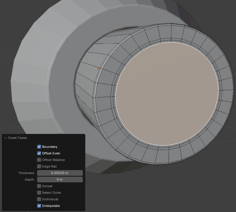
- Position the mouse in the 3D Viewport. Press I to create an inset and press Enter
- In the Inset Faces window, change the values as follows:
Thickness: 0.00025
Depth:     0
- On the top tool menu, click the Edge button
- Press and hold Alt
- Click one of the edges of the circle that is inside the others
- Release Alt
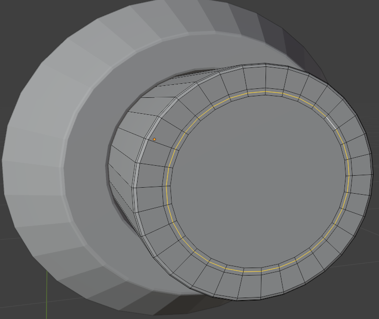
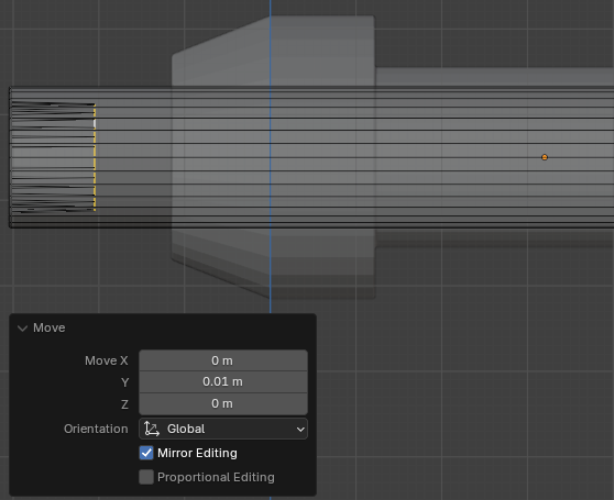
- Press G slightly and click
- In the Move window, change the values as follows:
Move: X: 0
       Y: 0.01
       Z: 0
- On the top menu, click the Face button
- Click a large vertical face to select it
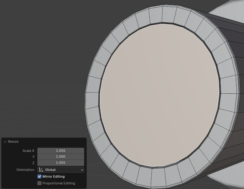
- Press S to resize the face and press Enter
- In the Resize window, change the X and the Z values as follows:
Scale: X: 1.055
       Z: 1.055
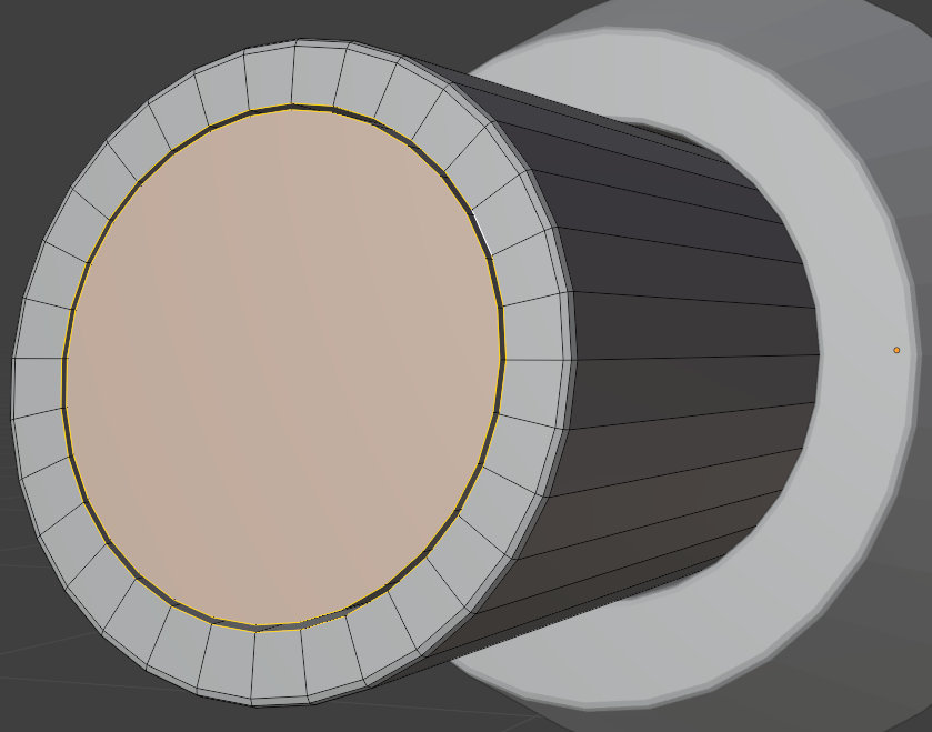
- On the top tool menu, click the Edge button
- While the face is still selected, press and hold Shift and Alt
- Click one of the edges of the next circle
- Release Shift and Alt
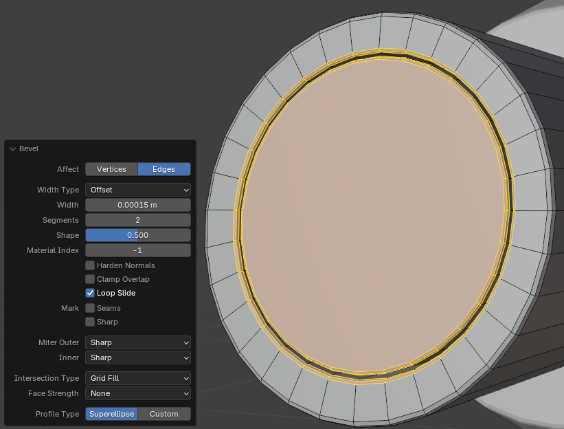
- To create bevels, press Ctrl + B, and press Enter
- In the Bevel window, change the values as follows:
Width:    0.00015
Segments: 2
- On the top menu, click the Face button
- Click the large face to select it
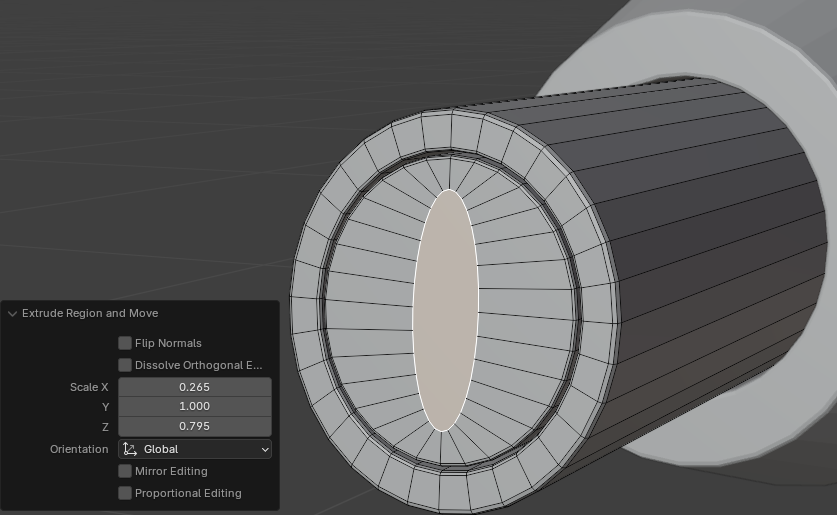
- Press E to extrude
- Then press S to resize, then press Enter
- In the Extrude Region and Move window, change the following values:
Scale X: 0.265
      Z: 0.795
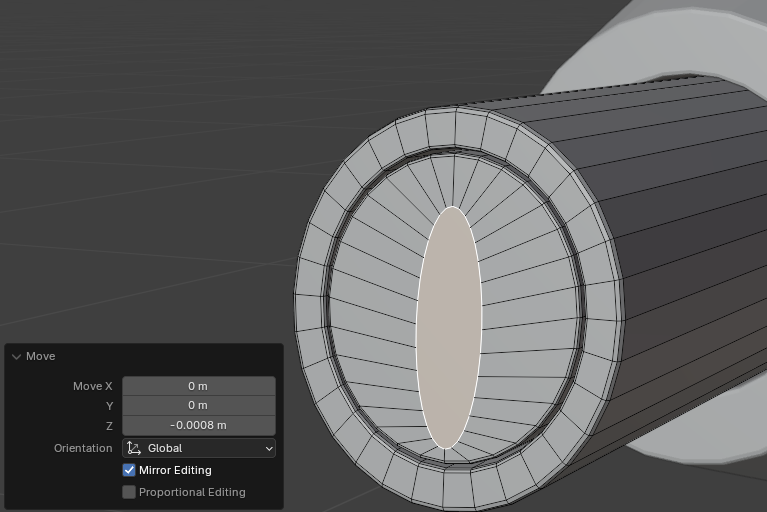
- While the face is selected, press G to move it and press Enter
- In the Move window, change the values as follows:
Move: X: 0
      Y: 0
      Z: -0.0008
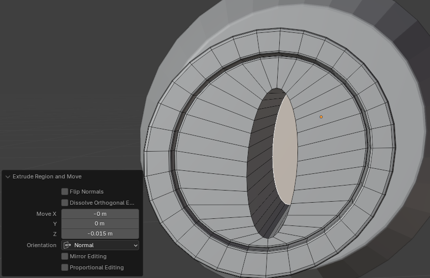
- While the face is still selected, press E to extrude and press Enter
- In the Extrude Region and Move window, change the following values:
Move X:  0
     Y:  0
     Z: -0.015
- On the top tool menu, click the Edge button
- While the bottom face is still selected, press and hold Shift and Alt
- Click one of the outside edges of the hole
- Release Shift and Alt
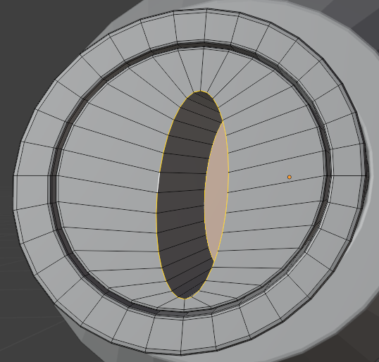
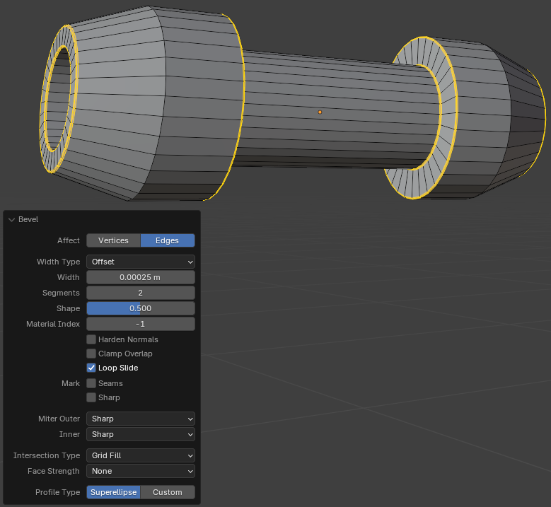
- To create bevels, press Ctrl + B, and press Enter
- In the Bevel window, change the values as follows:
Width:    0.00015
Segments: 2
- On the main menu of Blender, click Layout
Modeling a Handle Holder
A door handle is the part that a user holds in order to open a door. In this section, we will model one of the regular designs of door handles.
Practical Learning: Modeling a Handle Holder
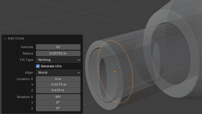
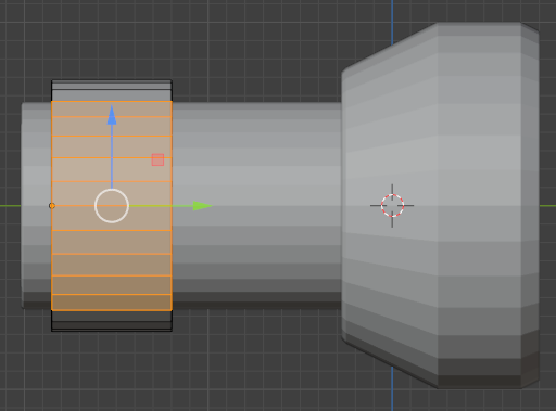
- On the top menu, click Add -> Mesh -> Circle
- On the right-top bar, click the X-Ray button

- In the Add Circle window, change the following values:
Radius:      0.00755
Fill Type:   Nothing
Location X:  0
         Y: -0.0275
         Z:  0.475
Rotation X:  90
         Y:  0
         Z:  0
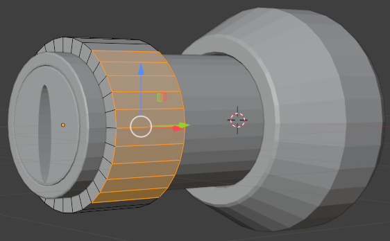
- Make sure the new circle is selected.
On the main menu of Blender, click Modeling
- Click and drag the Rotate button to display the shape in perspective
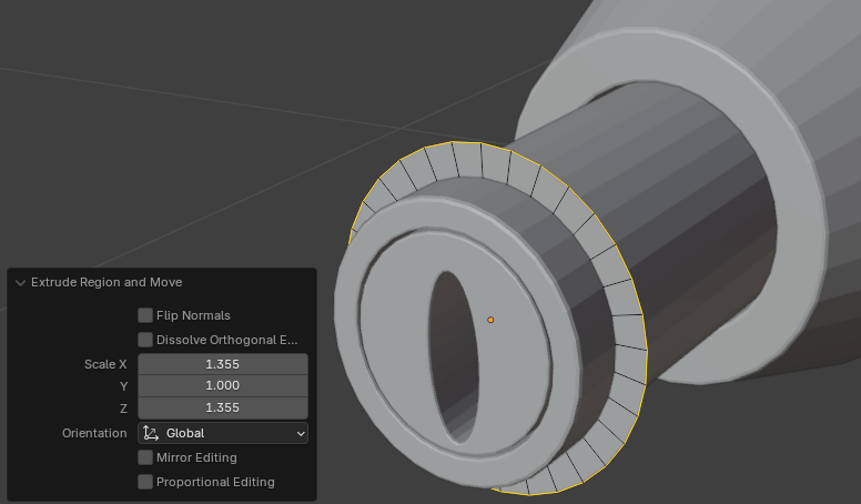
- To extrude the circle, press E
- To expand, press S
- Move the mouse slightly away and click
- In the Extrude Region and Move window, change the scale values to 1.355:
Scale X: 1.355
      Z: 1.355
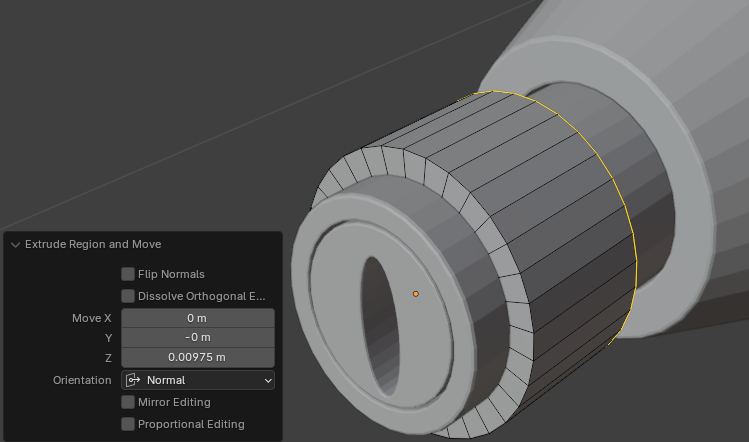
- On the top menu, click Select and click All
- To extrude, press E and press Enter
- In the Extrude Region and Move window, change the Move values as follows:
Move X: 0
     Y: 0
     Z: 0.00975
- On the top bar, click the Face button
- On the top bar, click View -> Viewpoint -> Right
- Draw a rectangle to select faces excluding the top and the bottom faces
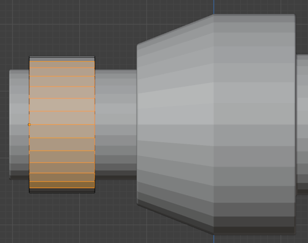
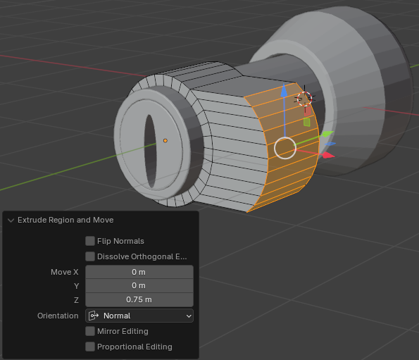
- Click and drag the Rotate button to display the shape in perspective
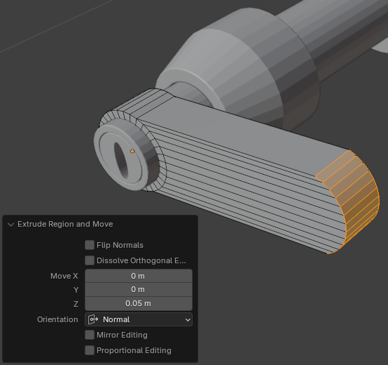
- To extrude, press E and press Enter
- In the Extrude Region and Move window, change the Z value to 2.5 values:
Move X: 0
     Y: 0
     Z: 0.05
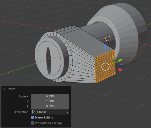
- To flatten the right side, press S, then press X, then type 0, and press Enter:
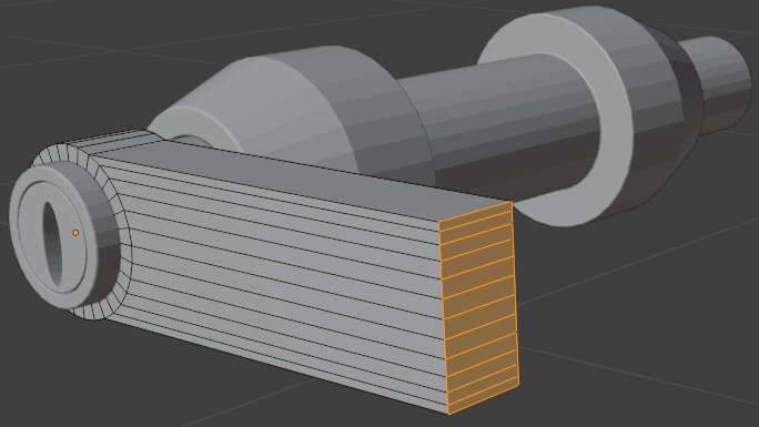
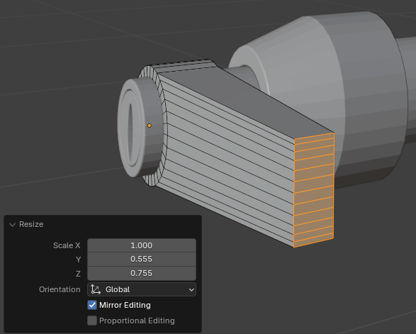
- While the faces are still selected, press S and press Enter
- In the Resize window, set the X, the Y, and the Z values to your liking:
Scale X: 1
      Y: 0.555
      Z: 0.755
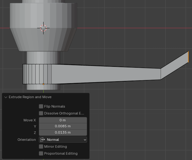
- On the top menu, click View -> Viewpoint -> Top
- Press E to extrude
- Move the mouse away slightly from the shape and click:
Move X: 0
     Y: 0.0085
     Z: 0.0135
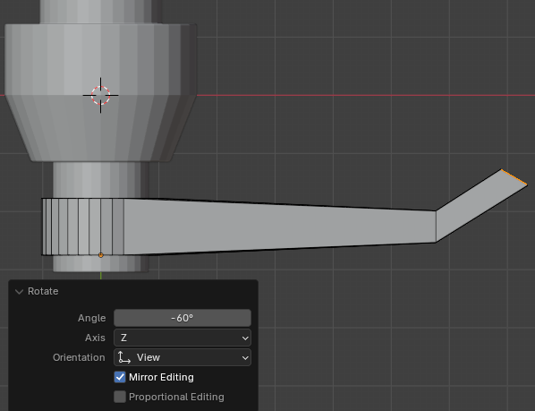
- To rotate the face, press R
- Type -60 for the angle and press Enter
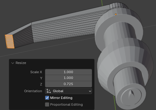
- While the face is still selected, press S to resize and press Enter
- In the Resize window, set the X, the Y, and the Z values:
Scale X: 1
      Y: 1
      Z: 0.725
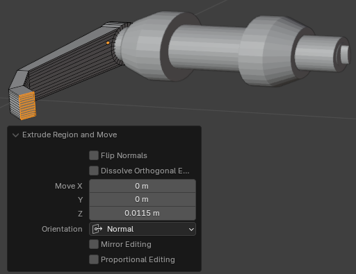
- While the face is still selected, press E to extrude
- Move the mouse a little and click:
Scale X: 0
      Y: 0
      Z: 0.0115
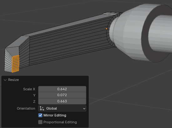
- While the face is still selected, press S to resize and press Enter
- In the Resize window, set the X, the Y, and the Z values:
Scale X: 0.6425
      Y: 0.0725
      Z: 0.6625
- While the face is still selected, press E to extrude
- Move the mouse very slightly and click:
Scale X: 0
      Y: 0
      Z: 0.0005
- While the face is still selected, press S to resize
- Move the mouse very slightly towards the shape and click
- In the Resize window, set the X, the Y, and the Z values:
Scale X: 0.685
      Y: 1
      Z: 0.685
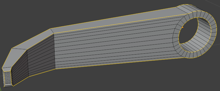
- To hide the other objects, in the numeric pad of the keyboard, press /
- On the top bar, click the Edge button
- Press and hold Alt
- Click one of the inside borders of the handle
- While Alt is still held, press and hold Shift
- Keep clicking the borders of the handle to select them:
- Press Ctrl + B to create a bevel on the borders of the handle
- Move the mouse slightly and click
- In the Bevel window, change the following values:
Width: 0.00025
Segments: 2
- To show the objects that were hidden, in the numeric pad of the leyboard, press /
- On the main menu of Blender, click Layout
- In the Properties window, click the Modifiers button

- Click the door cylinder to select it
- In the Properties window, click Add Modifier -> Generate -> Subdivision Surface
- Set the Levels Viewport to 2:
Levels Viewport: 2
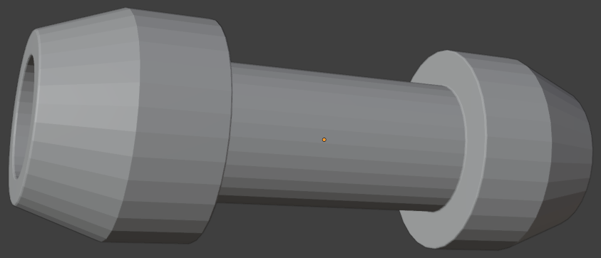
- Right-click the door handle and click Shade Smooth
- Click the base of the door handle to select it
- In the Properties window, click Add Modifier -> Generate -> Subdivision Surface
- Set the Levels Viewport to 2:
Levels Viewport: 2
- Right-click the door handle and click Shade Smooth
- Click the lock handle to select it
- In the Properties window, click Add Modifier -> Generate -> Subdivision Surface
- Set the Levels Viewport to 2:
Levels Viewport: 2
- Right-click the door handle and click Shade Smooth
- Position the mouse in the 3D Viewpoint and, in the numeric pad, press 3 to display the right view
- While the door handle is still selected, press Alt + D to duplicate and press Enter
- To rotate the duplicate handle, press R
- Type 180 and press Enter
- Press G to move the duplicate
- Then press Y to move it on the Y axis and position it on the other side of the central cylinder
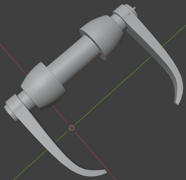
- To save the lock, on the main menu, click File -> Save
- Set the document name Door-Handle-External-1
- Click Save
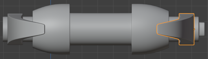
Varying a Handle Holder
As door handles come in various designs, in this section, we will modify the design from the previous section and get a variant of a door handle.
Practical Learning: Varying a Handle Holder
- On the top menu, click Add -> Mesh -> Circle
- On the right-top bar, click the X-Ray button
- In the Add Circle window, change the following values:
Radius:      0.505
Fill Type:   Nothing
Location X:  0
         Y: -1.85
         Z:  0
Rotation X:  90
         Y:  0
         Z:  0
- On the right-top bar, click the X-Ray button

- Make sure the new circle is selected.
On the main menu of Blender, click Modeling
- On the top bar, click View -> Viewpoint -> Front
- To extrude the circle, press E
- To expand, press S
- Move the mouse slightly away and click
- In the Extrude Region and Move window, change the scale values to 1.355:
Scale X: 1.355
      Z: 1.355
- Click and drag the Rotate button to display the shape in perspective
- On the top menu, click Select and click All
- To extrude, press E and press Enter
- In the Extrude Region and Move window, change the Move values as follows:
Move X: 0
     Y: 0
     Z: 0.65
- On the top bar, click the Face button
- On the top bar, click View -> Viewpoint -> Right
- Draw a rectangle to select faces excluding the top two and the bottom two faces
- Click and drag the Rotate button to display the shape in perspective
- To extrude, press E and press Enter
- In the Extrude Region and Move window, change the Z value to 0.75:
Move X: 0
     Y: 0
     Z: 0.75
- To flatten the right side, press S, then press X, then type 0, and press Enter
- While the face is still selected, press S and press Enter
- In the Resize window, set the X, the Y, and the Z values to your liking:
Scale X: 0.635
      Y: 1
      Z: 0.405
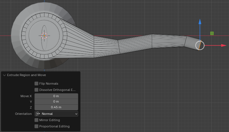
- On the top menu, click View -> Viewpoint -> Front
- Click the blue arrow down to move the face and make the bottom border almost horizontal
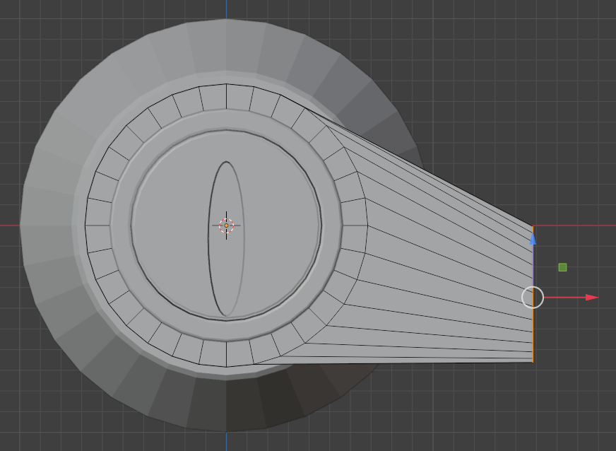
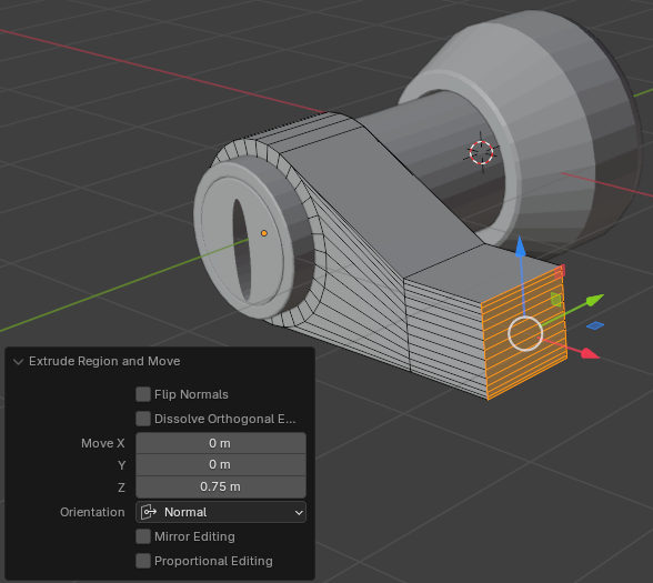
- Press E to extrude
- Move the mouse away slightly from the shape:
Move X: 0
     Y: 0
     Z: 0.75
- Press S, then press Z to resize only vertically
- Move the mouse slightly towards the shape and click
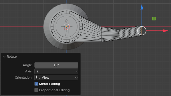
- To rotate the face, press R
- Type -10 for the angle and press Enter
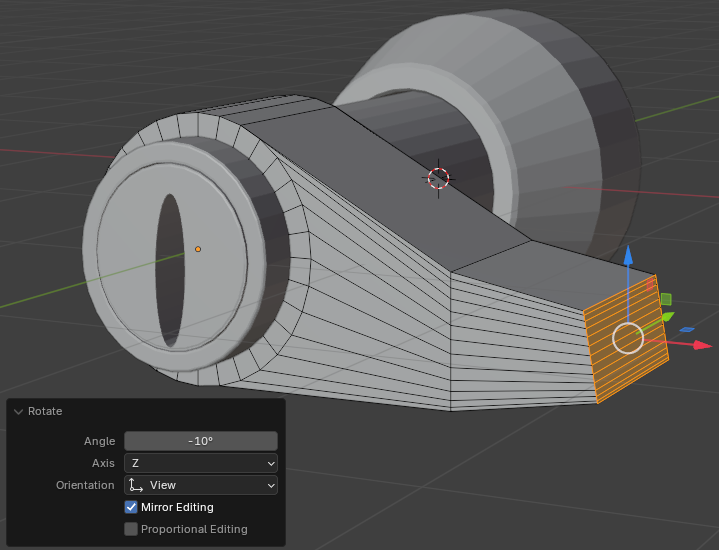
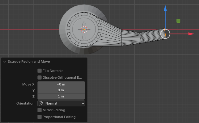
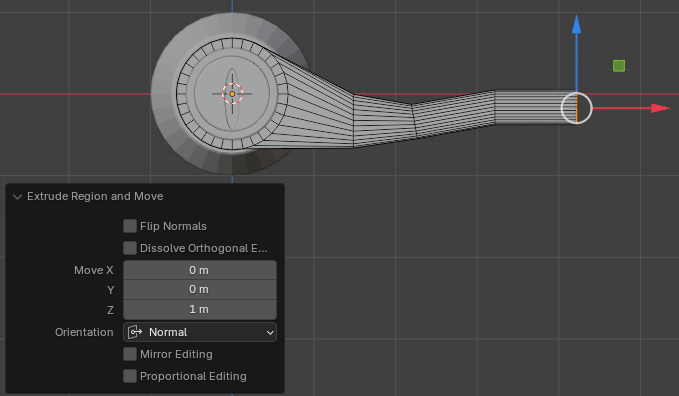
- While the face is still selected, press E to extrude and press Enter
- Move the mouse a little bit to the right:
Move X: 0
      Y: 0
      Z: 1
- While the face is still selected, to rotate it, press R
- Type 10 for the angle and press Enter
- While the face is still selected, press E to extrude
- Move the mouse a little and click:
Scale X: 0
      Y: 0
      Z: 1
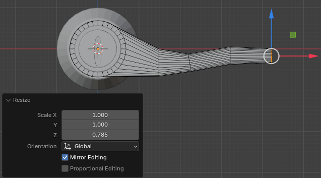
- While the face is still selected, press S to resize and press Z to resize vertically
- Move the mouse a little toward the shape and click:
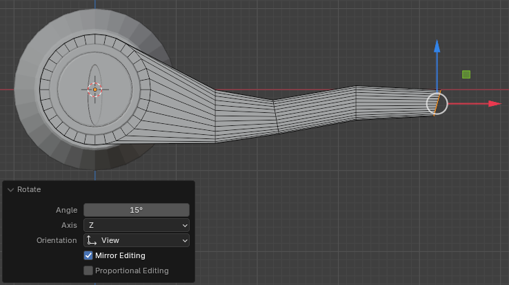
- While the face is still selected, to rotate it, press R
- Type 15 for the angle and press Enter
- While the face is still selected, press E to extrude
- Move the mouse a little to the right:
Scale X: 0
      Y: 0
      Z: 0.065
- While the face is still selected, press S to resize
- Move the mouse a little toward the shape and click
- While the face is still selected, press E to extrude
- Move the mouse very slightly and click:
- While the face is still selected, press S to resize
- Move the mouse a little toward the shape and click
- To hide the other objects, in the numeric pad of the keyboard, press /
- On the main menu of Blender, click Layout
- In the Properties window, click the Modifiers button
- In the Properties window, click Add Modifier -> Generate -> Subdivision Surface
- Set the Levels Viewport to 2:
Levels Viewport: 2
- Right-click the door handle and click Shade Smooth
- Click the door cylinder to select it
- In the Properties window, click Add Modifier -> Generate -> Subdivision Surface
- Set the Levels Viewport to 2:
Levels Viewport: 2
- Right-click the door handle and click Shade Smooth
- Click the base of the door handle to select it
- In the Properties window, click Add Modifier -> Generate -> Subdivision Surface
- Set the Levels Viewport to 2:
Levels Viewport: 2
- Right-click the door handle and click Shade Smooth
- To save, on the main menu, click File -> Save As...
- Set the file naame to Door-Handle-External-2
- Click the Save As button
- Release Alt
- Position the mouse on the cylinder between the previously created loop cuts. Press Ctrl + R to create some loop cuts
- While the circles are still selected, press and hold Shift and Alt
- On the top bar, click the Face button
- Rotate the shape so you can access its back face
- Click the back face to select it:
- Position the mouse in the 3D Viewport. Press E to extrude, then press S to resize, then press Enter
- Rotate the object to see the front face
- Click the front vertical face to select it
- Press E to extrude and press Enter
- In the Extrude Region and Move window, change the Z value to 0.0125:
Move Z: 0.0125
- Position the mouse in the 3D Viewport. Press S to resize. Slightly move the mouse and click
- In the Resize window, change the X and the Z values to 0.985 each:
Scale: X: 0.985
       Z: 0.985
- Position the mouse in the 3D Viewport. Press S to resize. Slightly move the mouse and click
- In the Resize window, change the X and the Z values to 0.985 each:
Scale: X: 0.985
       Z: 0.985
- Position the mouse in the 3D Viewport. Press G. Move the mouse slightly and click
- In the Move window, change the values as follows:
Move X:  0
     Y: -0.0125
     Z:  0
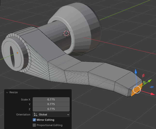
- Position the mouse in the 3D Viewport. Press S to resize. Move the mouse slightly and click
- In the Move window, change the values as follows:
Scale: X: 0.995
       Z: 0.995
- Position the mouse in the 3D Viewport. Press E to extrude, then press S to resize, then press Enter
- In the Extrude Region and Move window, change the X and the Z values to 0.95 each:
Scale X: 0.985
       Z: 0.985
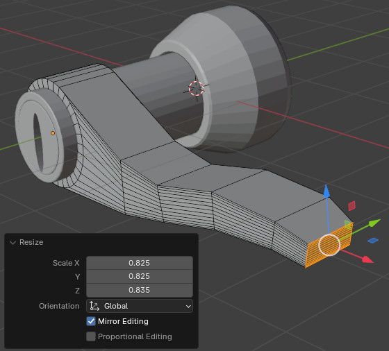
- Position the mouse on the 3D Viewport window. Press E to extrude, then press S to resize, then press Enter
- In the Extrude Region and Move window, change the X and the Z values to 0.95 each:
Scale: X: 0.825
       Z: 0.825
- Position the mouse on an empty area of the 3D Viewport window. Press E to extrude, then press S to resize, then press Enter
- In the Extrude Region and Move window, change the values to 0.95 each:
Scale: X: 0.985
       Z: 0.985
- Position the mouse in the 3D Viewport. Press G. Move the mouse slightly and click
- In the Move window, change the values as follows:
Move X: 0
     Y: 0.0125
     Z: 0
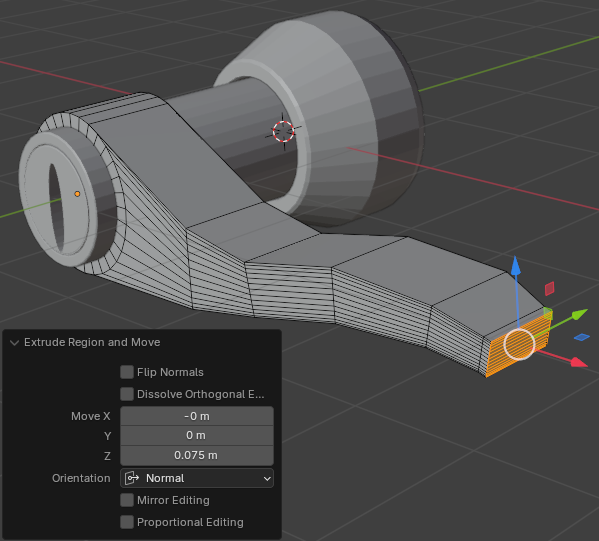
- In the Extrude Region and Move window, change the following values:
Move X:  0
     Y:  0
     Z: -0.975
- To hide the other part, in the numeric part of the keyboard, press /
- Press I. Move the mouse slightly towards the center of the face and click