Modeling the Lock Base
 Practical Learning: Modeling the Lock Base
- Start Blender
- Click the default cube to select it
- Press H to hide it
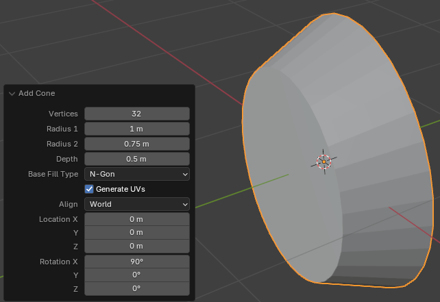
- Position the mouse in the 3D Viewport. Then, press Shift + A -> Mesh -> Cone
- In the bottom-left section of the 3D Viewport, click Add Cube to expand its window
- In the Add Cube window, change the following characteristics:
Radius 2:   0.75
Depth:      0.5
Rotation X: 90
- To edit the cone, on the top-main menu of Blender, click Modeling
- Press and hold the middle button of the mouse. Then move the mouse to rotate the cone to see the large back face, and release the mouse
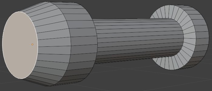
- Position the mouse in the 3D Viewport. Type 3 to select the Face option
- Click the large vertical face to select it
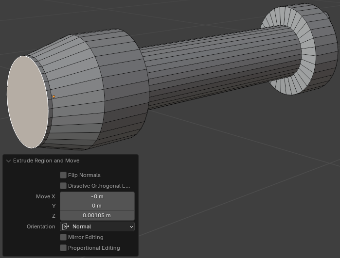
- Press E to extrude and press Enter
- In the bottom-left section of the 3D Viewport, click Extrude Region and Move to expand its window
- In the Extrude Region and Move window, change the Z value to 0.45:
Move Z: 0.45
- Position the mouse on an empty area of the 3D Viewport window. Press E to extrude and press Enter
- In the Extrude Region and Move window, change the Z value to 0.1:
Move Z: 0.1
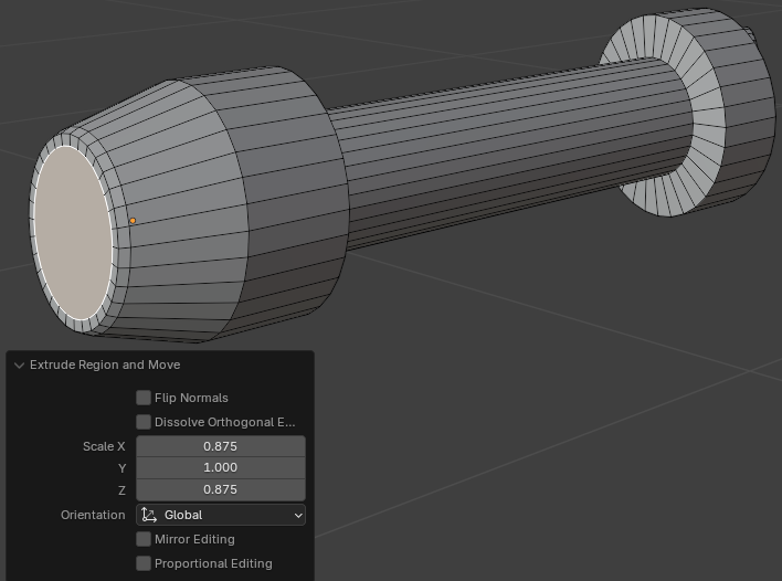
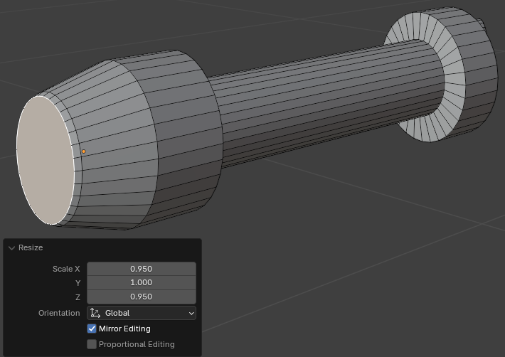
- Position the mouse in the 3D Viewport. Press S to resize the face. Move the mouse slightly and click
- In the Resize window, change the X and the Z values to 0.95 each:
Scale: X: 0.95
       Z: 0.95
- Position the mouse in the 3D Viewport. Press E to extrude, then press S to resize, then press Enter
- In the Extrude Region and Move window, change the X and the Z value to 0.55 each:
Scale: X: 0.55
       Z: 0.55
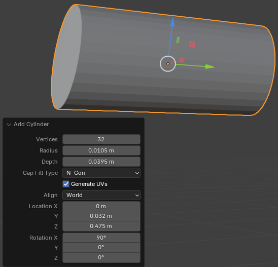
- Rotate the cone to see the front face
- Click the front vertical face to select it
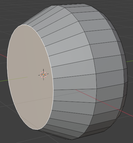
- Press E to extrude and press Enter
- In the Extrude Region and Move window, change the Z value to 0.0125:
Move Z: 0.0125
- Position the mouse in the 3D Viewport. Press S to resize. Slightly move the mouse and click
- In the Resize window, change the X and the Z values to 0.985 each:
Scale: X: 0.985
       Z: 0.985
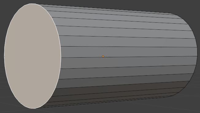
- Position the mouse in the 3D Viewport. Press S to resize. Slightly move the mouse and click
- In the Resize window, change the X and the Z values to 0.985 each:
Scale: X: 0.985
       Z: 0.985
- Position the mouse in the 3D Viewport. Press G. Move the mouse slightly and click
- In the Move window, change the values as follows:
Move X:  0
     Y: -0.0125
     Z:  0
- Position the mouse in the 3D Viewport. Press S to resize. Move the mouse slightly and click
- In the Move window, change the values as follows:
Scale: X: 0.995
       Z: 0.995
- Position the mouse in the 3D Viewport. Press E to extrude, then press S to resize, then press Enter
- In the Extrude Region and Move window, change the X and the Z values to 0.95 each:
Scale X: 0.985
       Z: 0.985
- Position the mouse on the 3D Viewport window. Press E to extrude, then press S to resize, then press Enter
- In the Extrude Region and Move window, change the X and the Z values to 0.95 each:
Scale: X: 0.825
       Z: 0.825
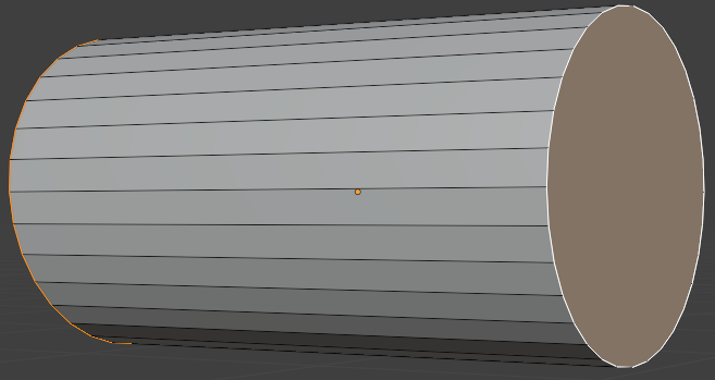
- Position the mouse on an empty area of the 3D Viewport window. Press E to extrude, then press S to resize, then press Enter
- In the Extrude Region and Move window, change the values to 0.95 each:
Scale: X: 0.985
       Z: 0.985
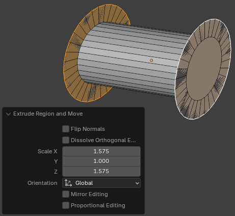
- Position the mouse in the 3D Viewport. Press G. Move the mouse slightly and click
- In the Move window, change the values as follows:
Move X: 0
     Y: 0.0125
     Z: 0
- Position the mouse on an empty area of the 3D Viewport window. Press E to extrude, then press S to resize, then press Enter
- In the Extrude Region and Move window, change the values to 0.95 each:
Scale: X: 0.985
       Z: 0.985
- Position the mouse in the 3D Viewport. Press G. Move the mouse slightly and click
- In the Move window, change the values as follows:
Move X: 0
     Y: 0.0125
     Z: 0
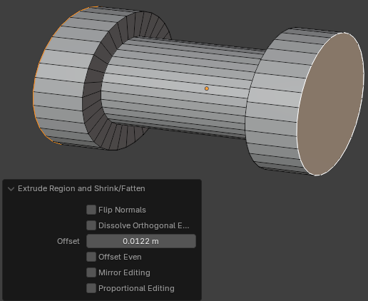
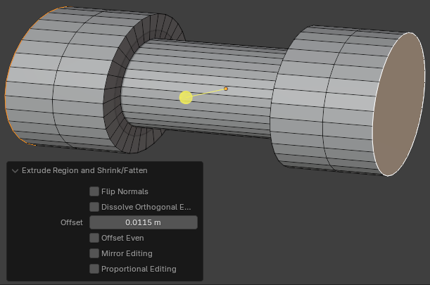
- While the face is still selected, press E then press Enter
- In the Extrude Region and Move window, change the following values:
Move X:  0
     Y:  0
     Z: -0.975
- Press I. Move the mouse slightly towards the center of the face and click
- On the top-main menu of Blender, click Layout
Modeling a Door Handle Cylinder
.
 Practical Learning: Modeling a Door Handle Cylinder
- To add an object, press Shift + A -> Add -> Cylinder
- In the Add Cylinder window, change the following values:
Radius:  0.565
Depth:   2.5
Location Y: -0.755
Rotation X:  90
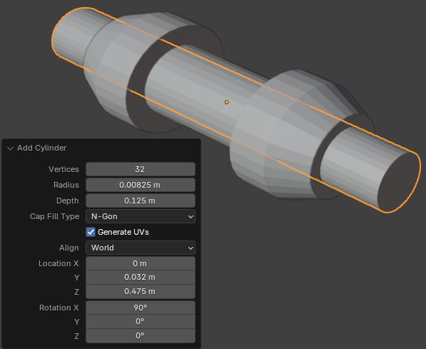
- To edit the cube, on the top-main menu of Blender, click Modeling
- To hide the other part, in the numeric part of the keyboard, press /
- Click and drag the Rotate button so you can see the back face
- Position the mouse in the 3D Viewport and press 3 to select the Face option
- Click the large vertical face
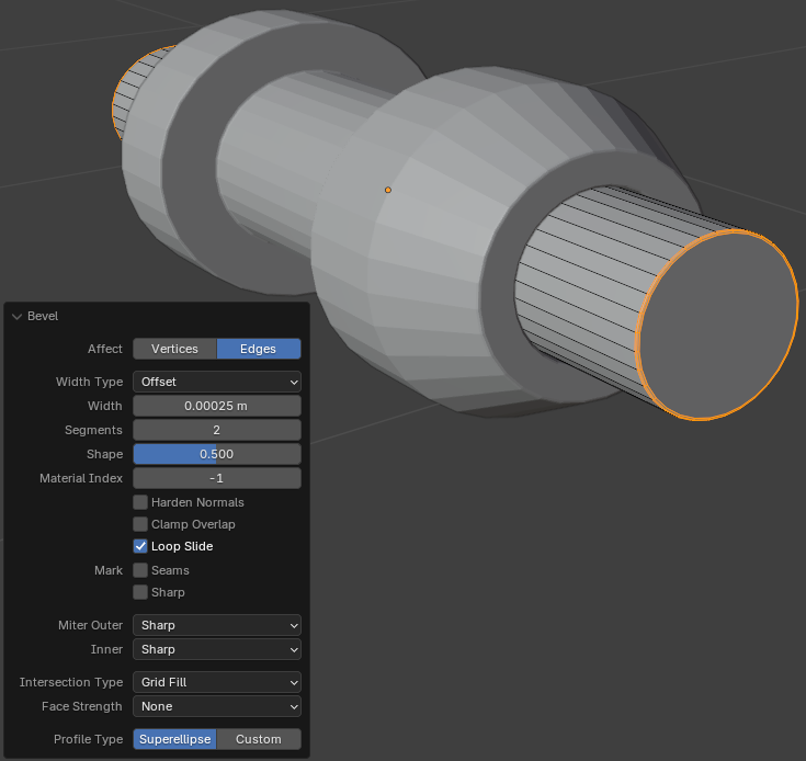
- Press I to create an inset and press Enter
- In the Inset Faces window, change the values as follows:
Thickness: 0.025
Depth:     0.025
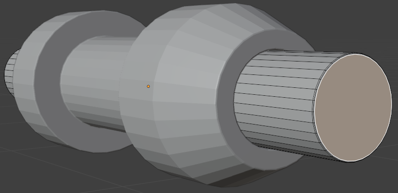
- Position the mouse in the 3D Viewport. Press I to create an inset and press Enter
- In the Inset Faces window, change the values as follows:
Thickness: 0.025
Depth:     0.0125
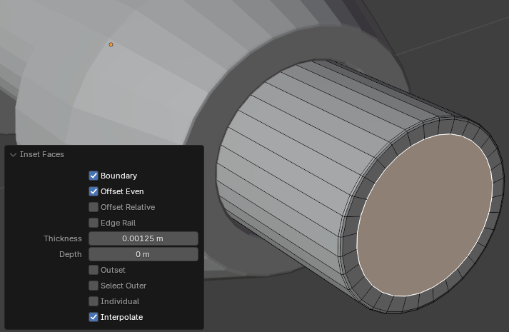
- Click and drag the Rotate button so you can see the front face
- Click the large vertical face
- Position the mouse in the 3D Viewport. Press I to create an inset and press Enter
- In the Inset Faces window, change the values as follows:
Thickness: 0.025
Depth:     0.025
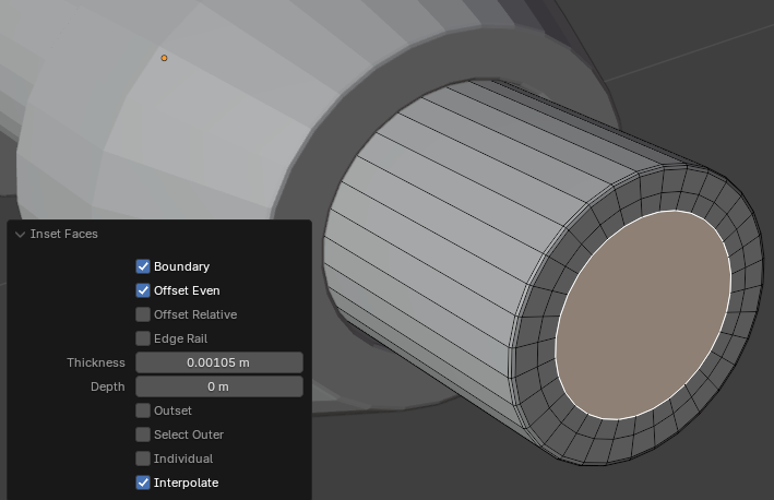
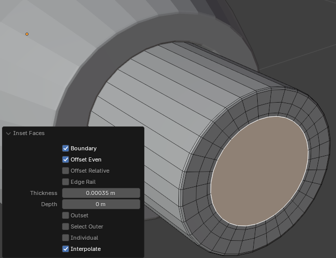
- Position the mouse in the 3D Viewport. Press I to create an inset and press Enter
- In the Inset Faces window, change the values as follows:
Thickness: 0.025
Depth:     0.0125
Modeling a Handle Holder
.
 Practical Learning: Modeling a Handle Holder
- Position the mouse in the 3D Viewport. Then, press Shift + A -> Mesh -> Cube
- In the Add Cube window, change the following values:
Size:        1.25
Location X:  0
         Y: -1.275
         Z:  0
- On the left toolbar, click the Move button

- If the Face option is not currently selected, on the top toolbar, click the Face button
 .
.
Rotate the view so you can access the back face.
Click the back face of the cube
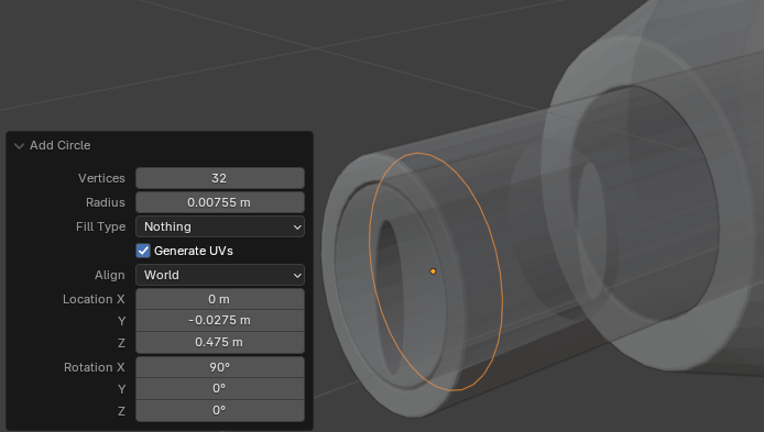
- Move that back face towards the other face:
Move X: 0
     Y: -0.55
     Z: 0
- On the top bar, click the Edge button

- Click one of the right edges
- Press and hold Shift
- Click the other edge
- Release Shift
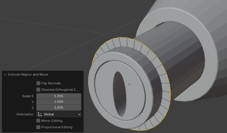
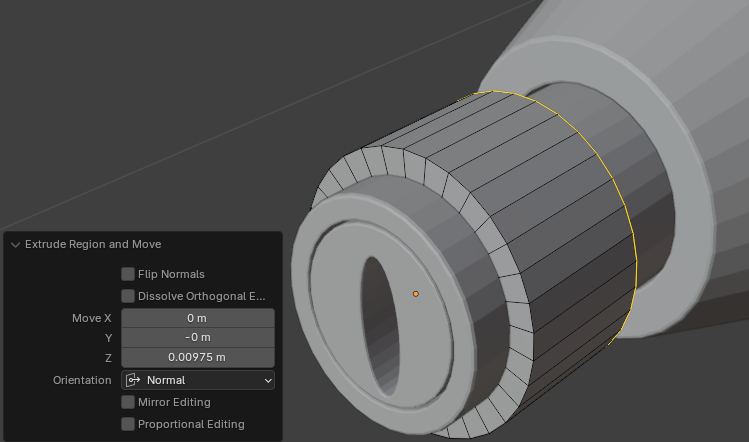
- Press Ctrl + B to create bevels and press Enter
- In the Bevel window, change the following values:
Width: 0.55
Segments: 6
Shape:    0.465
- Rotate the shape so you can see the other face
- On the top bar, click the Face button

- Click the right face of the cube
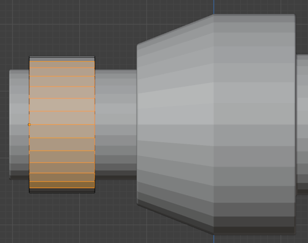
- Move the face towards the positive values in the X axis:
Move X: 2.5
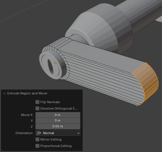
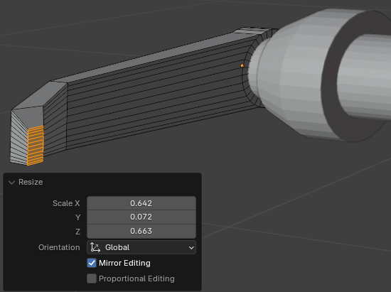
- While the right face is still selected, press S to resize
- Move the mouse slightly and click
- In the Resize window, set the X, the Y, and the Z values to your liking:
Scale X: 0.635
      Y: 0.635
      Z: 0.755
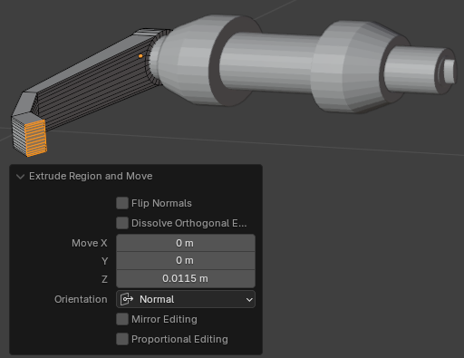
- Press E to extrude
- Using the red X, move the mouse away from the shape:
Move X: 0.45
     Y: 0
     Z: 0.85
- While the right face is still selected, press S to resize
- Move the mouse slightly towards the shape and click
- In the Resize window, set the X, the Y, and the Z values:
Scale X: 0.825
      Y: 0.725
      Z: 0.825
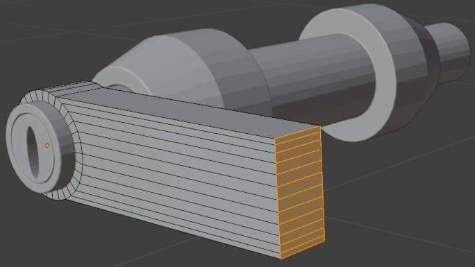
- To rotate the face, press R
- Press Z to rotate horizontaly
- Type 60 for the angle and press Enter
- While the face is still selected, press E to extrude
- Move the mouse a little and click:
Scale X: 0
      Y: 0
      Z: 0.575
- While the face is still selected, press S to resize
- Move the mouse slightly towards the shape and click
- In the Resize window, set the X, the Y, and the Z values:
Scale X: 0.825
      Y: 0.825
      Z: 0.825
- While the face is still selected, press E to extrude
- Move the mouse very slightly and click:
Scale X: 0
      Y: 0
      Z: 0.065
- While the face is still selected, press S to resize
- Move the mouse very slightly towards the shape and click
- In the Resize window, set the X, the Y, and the Z values:
Scale X: 0.885
      Y: 0.885
      Z: 0.885
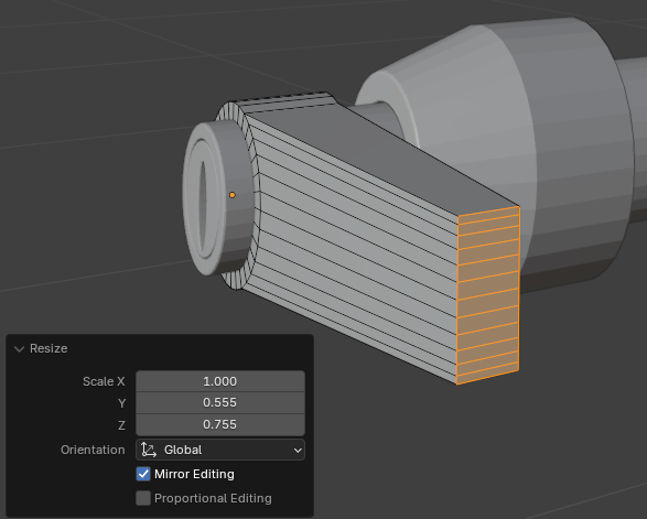
- On the top bar, click the Edge button

- Press and hold Alt
- Click one of the borders of the handle
- While Alt is still held, press and hold Shift
- Keep clicking the other parts of the border to select the whole border:
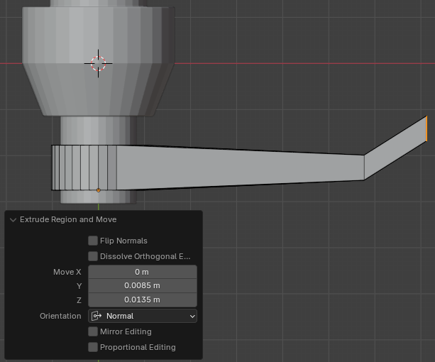
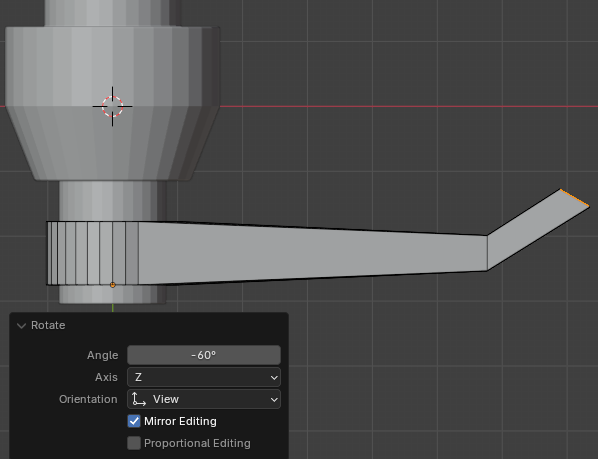
- Press Ctrl + B to create a bevel on the borders of the handle
- Move the mouse slightly and click
- In the Bevel window, change the following values:
Width: 0.025
Segments: 2
Shape: 0.465
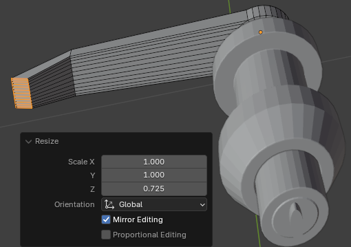
- On the main menu of Blender, click Layout
- To save, on the main menu, click File -> Save
- Set the file naame to Door-Handle-External-1
- Click Save Blender File
- In the Properties window, click the Modifiers button

- In the Properties window, click Add Modifier -> Generate -> Subdivision Surface
- Set the Levels Viewport to 2:
Levels Viewport: 2
- Right-click the door handle and click Shade Smooth
- Click the base of the door handle to select it
- In the Properties window, click Add Modifier -> Generate -> Subdivision Surface
- Set the Levels Viewport to 2:
Levels Viewport: 2
- Right-click the door handle and click Shade Smooth
- To save, on the main menu, click File -> Save As...
- Set the file naame to Door-Handle-External-2
- Click Save As
![]() Practical Learning: Modeling the Lock Base
Practical Learning: Modeling the Lock Base


![]() Practical Learning: Modeling a Door Handle Cylinder
Practical Learning: Modeling a Door Handle Cylinder


![]() Practical Learning: Modeling a Handle Holder
Practical Learning: Modeling a Handle Holder


