Modeling Simple Door Locks
Modeling Simple Door Locks
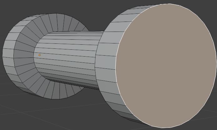
Modeling a Basic Door Lock
Houses use doors to keep some of their areas safe. As a matter of fact, houses use various types of doors. To apply these safety measures, doors use locks. Doors in turn use various types of locks. For example, external and internal doors may use different types of locks. Normally, locks used on external doors use keys. In this exercise, we will model a simple door lock.
![]() Practical Learning: Modeling a Basic Door Lock
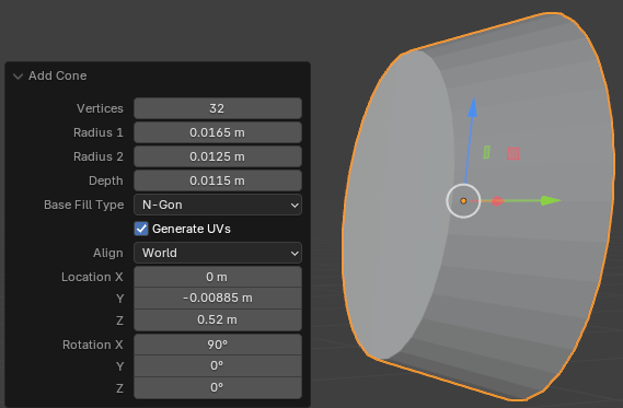
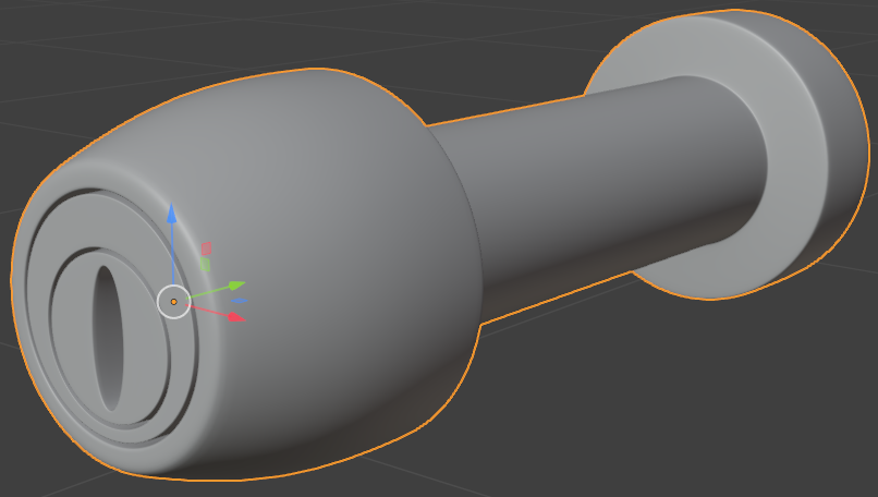
Practical Learning: Modeling a Basic Door Lock
Radius 1:    0.0165
Radius 2:    0.0125
Depth:       0.0115
Location X:  0
         Y: -0.00885
         Z:  0.52
Rotation X: 90
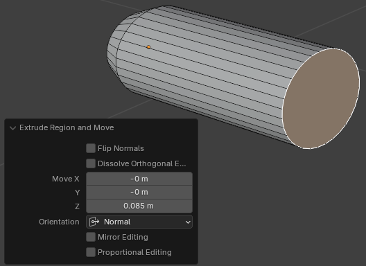
Move Z: 0.085
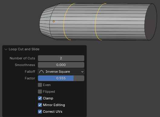
Factor: 0.555
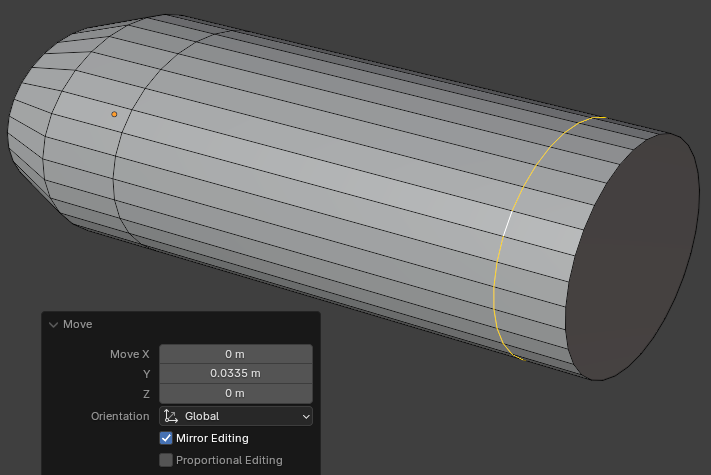
Move X: 0
     Y: 0.0335
     Z: 0
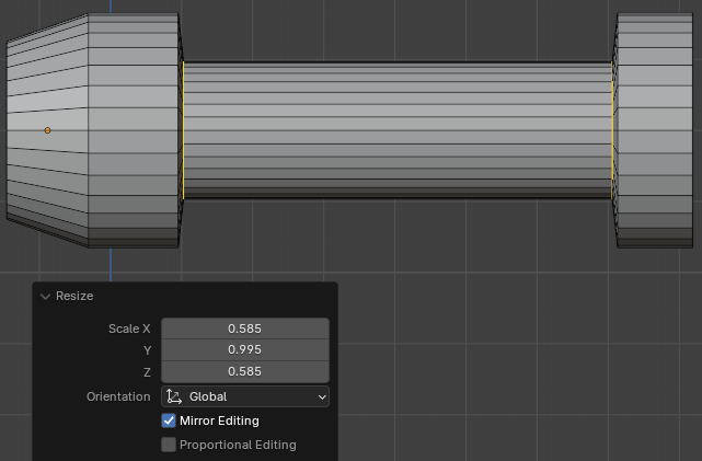
Scale X: 0.585
      Y: 0.995
      Z: 0.585
Scale: X: 0.955
      Z: 0.955
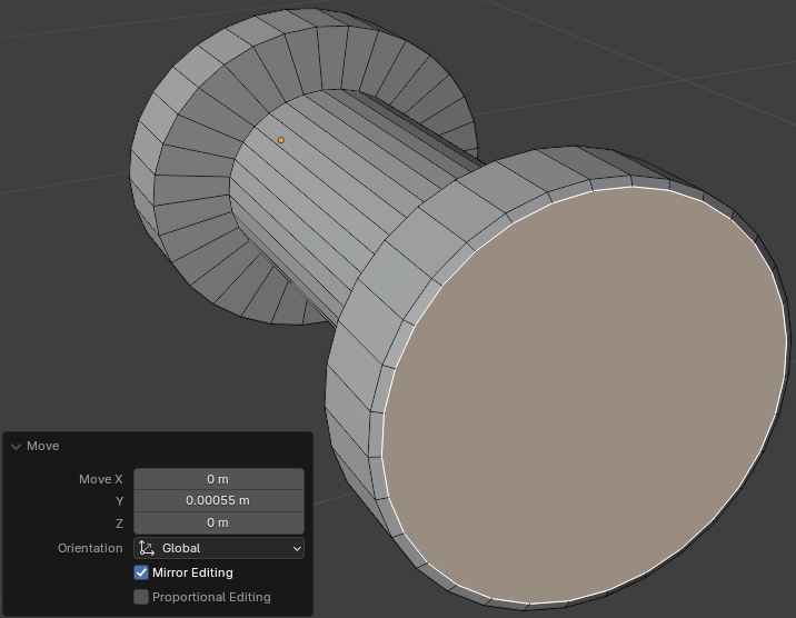
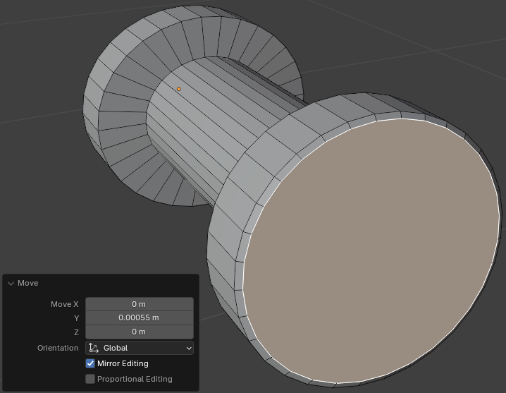
Move: X: 0
      Y: 0.00055
      Z: 0
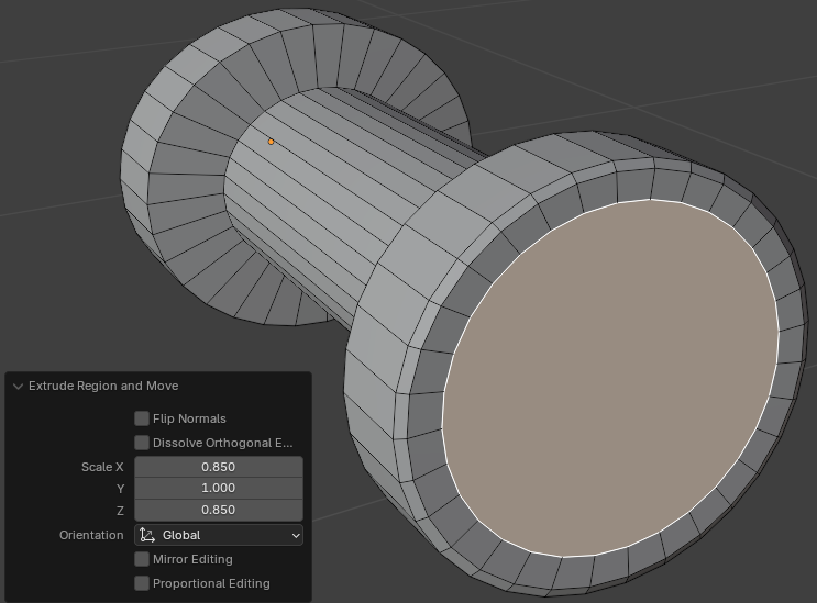
Scale: X: 0.85
      Z: 0.85
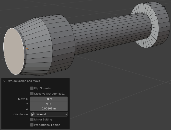
Move Z: 0.00105
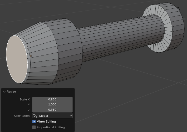
Scale: X: 0.95
       Z: 0.95
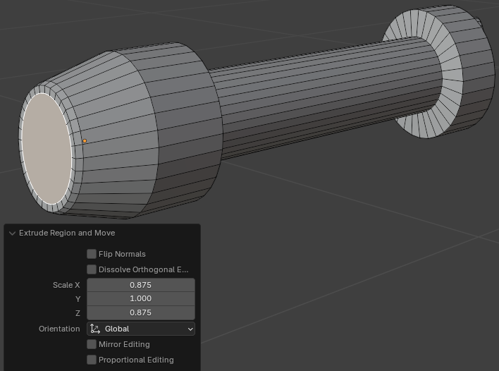
Scale: X: 0.875
       Z: 0.875
Scale X: 0.95
       Z: 0.95
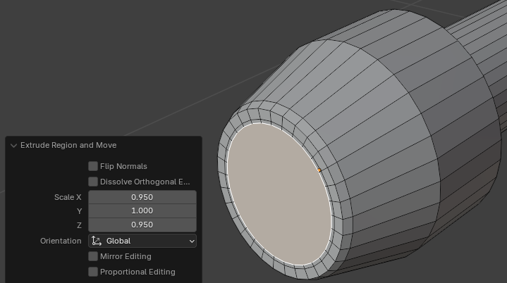
Scale: X: 0.985
       Z: 0.985

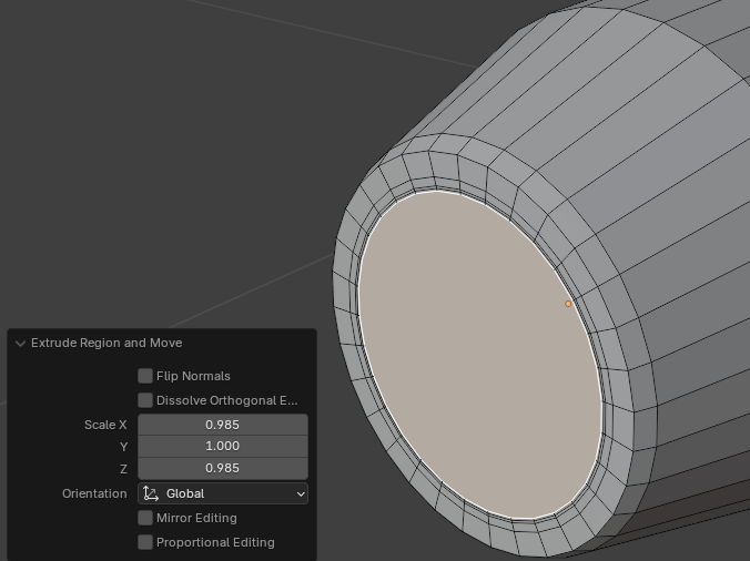
Scale: X: 0.985
       Z: 0.985
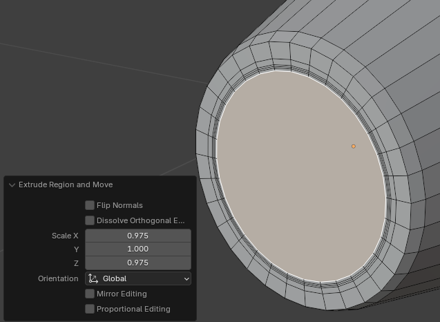
Scale: X: 0.975
       Z: 0.975
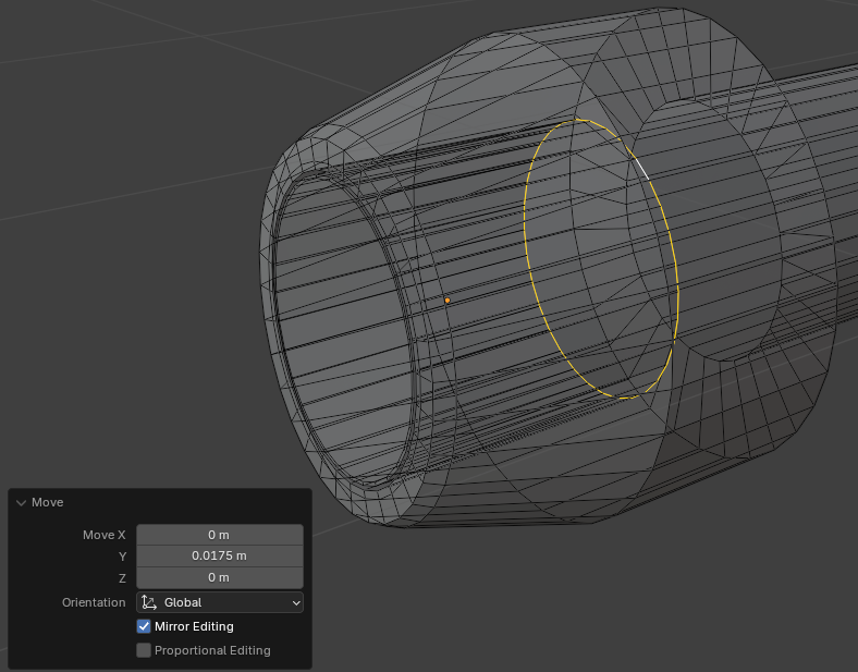
Move: X: 0
      Y: 0.0175
      Z: 0
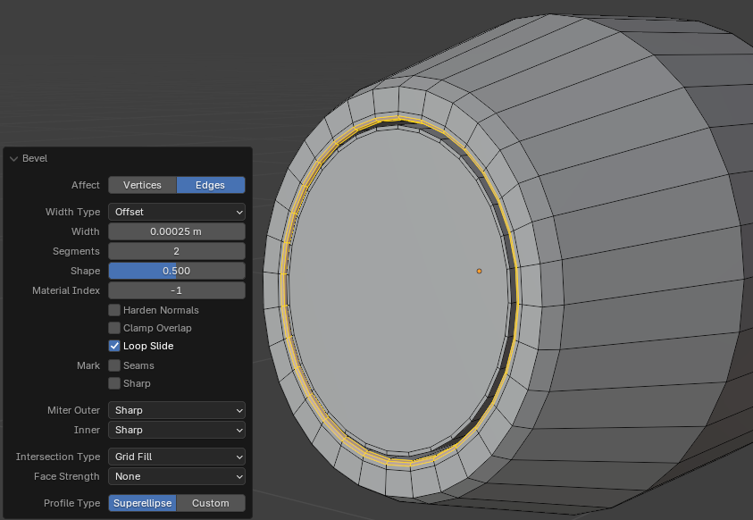
Width:    0.00025
Segments: 2
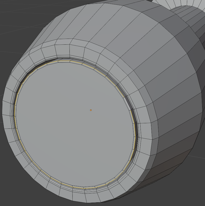
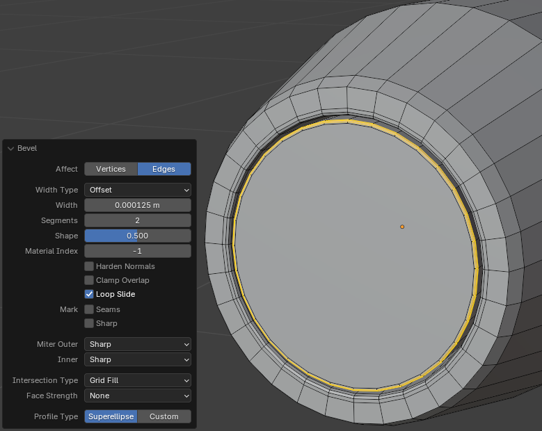
Width:    0.000125
Segments: 2
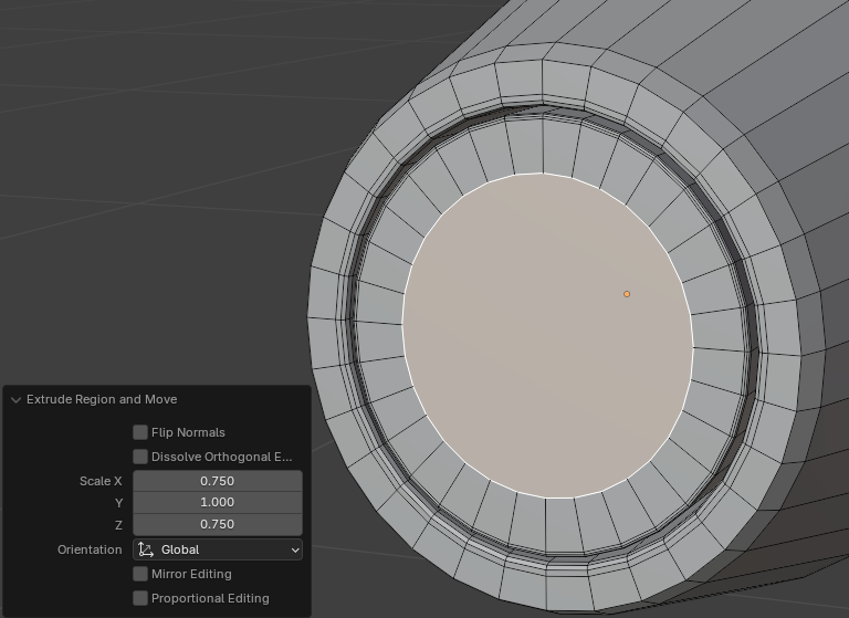
Scale X: 0.75
      Z: 0.75
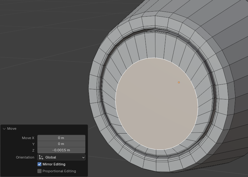
Move X:  0
          Y:  0
          Z: -0.0015
Move X: 0.975
Z: 0.975Move X: 0.975
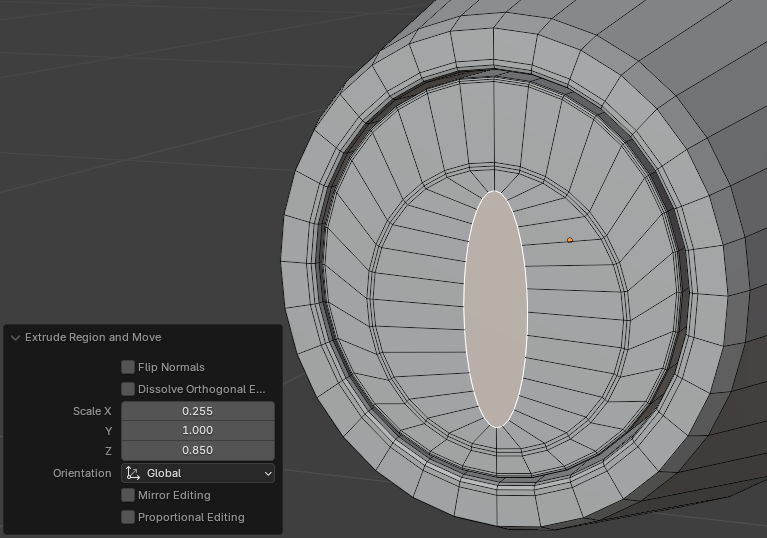
Z: 0.975Move X: 0.255
Z: 0.85
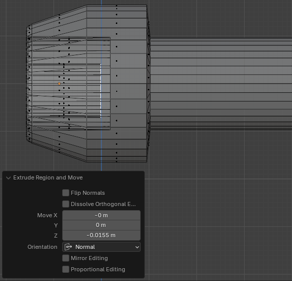
Move X:  0
     Y:  0
     Z: -0.0155
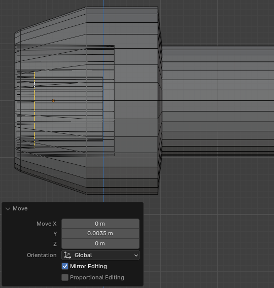
Move: X: 0
       Y: 0.0035
       Z: 0
Levels Viewport: 2
|
|
|||
| Medium House | Copyright © 2016-2025, FunctionX | Monday 26 August 2024, 12:30 | External Door Handles |
|
|
|||