Modeling Simple Door Locks
Modeling Simple Door Locks
Modeling a Basic Door Lock
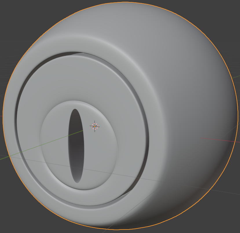
Houses use doors to keep some of their areas safe. As a matter of fact, houses use various types of doors. To apply these safety measures, doors use locks. Doors in turn use various types of locks. For example, external and internal doors may use different types of locks. Normally, locks used on external doors use keys. In this exercise, we will model a simple door lock.
![]() Practical Learning: Modeling a Basic Door Lock
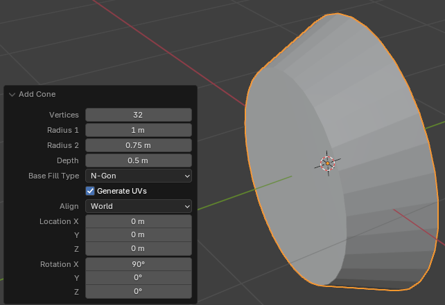
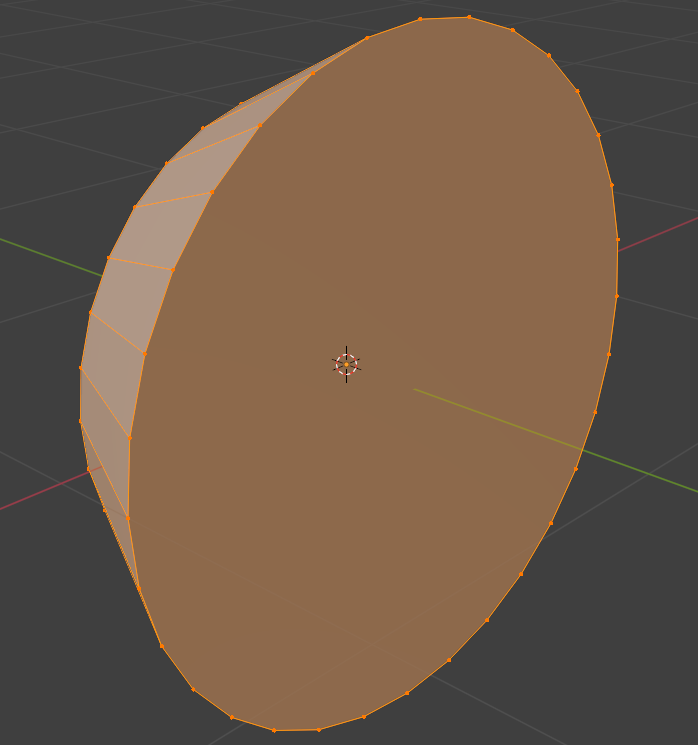
Practical Learning: Modeling a Basic Door Lock
Radius 2: 0.75
Depth:    0.5
Align:    View
Move Z: 0.45
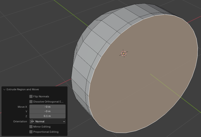
Move Z: 0.1
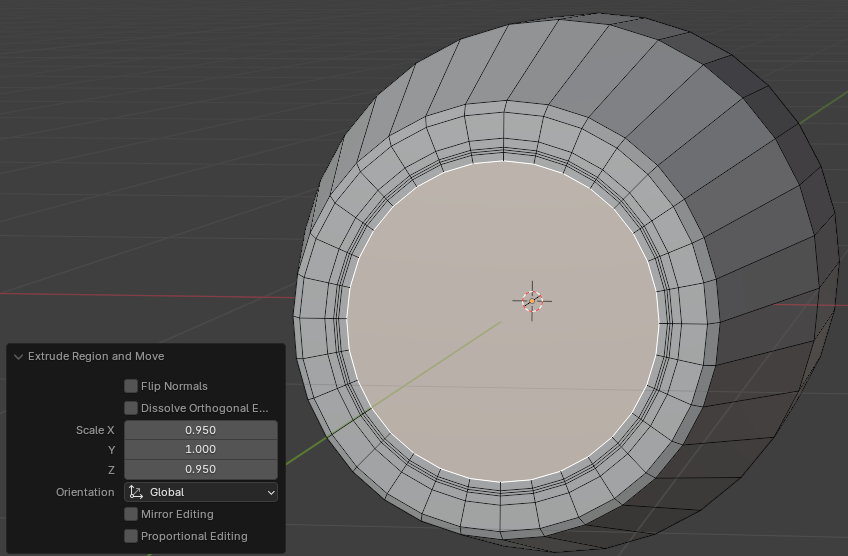
Scale: X: 0.95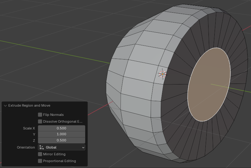
Z: 0.95Scale: X: 0.5
Y: 0.5
Z: 0.5

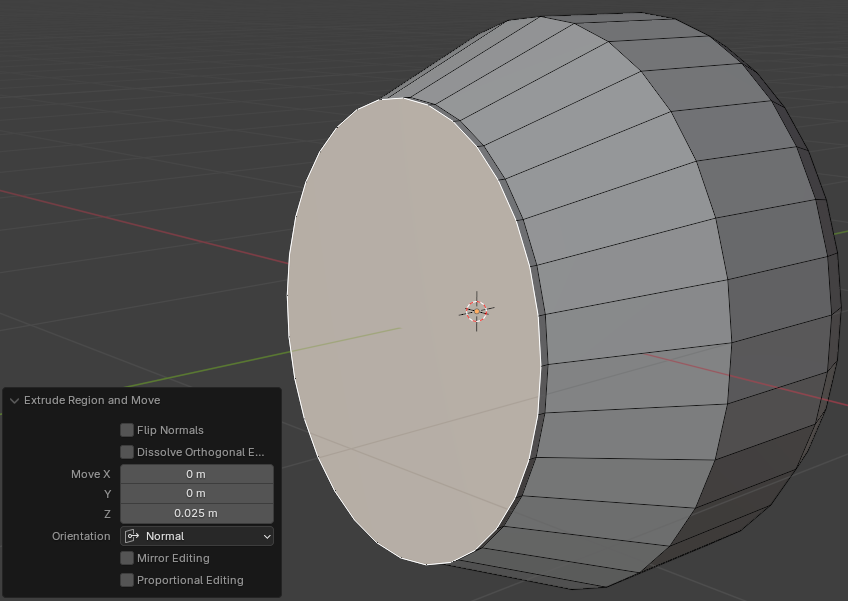
Move Z: 0.025
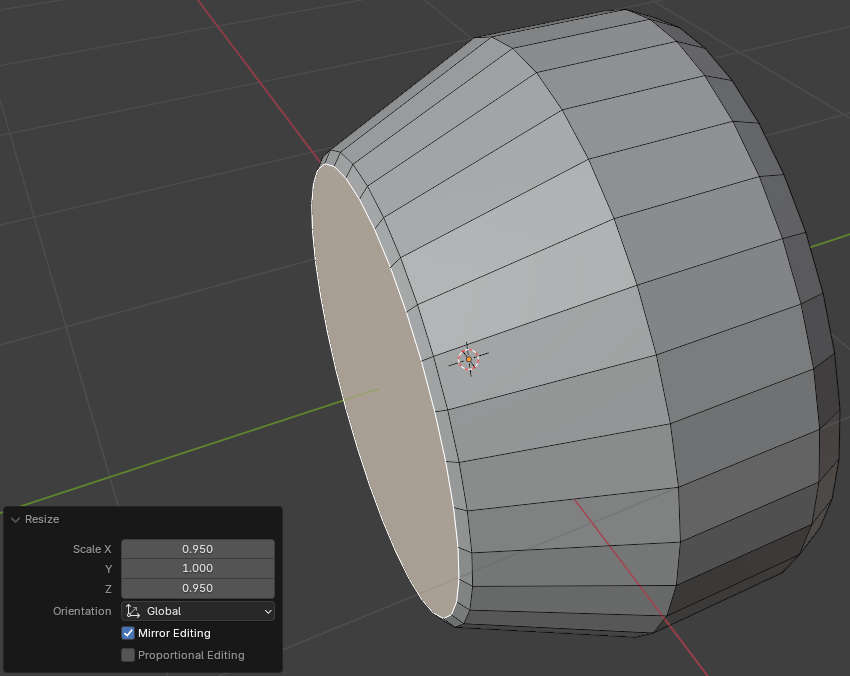
Scale: X: 0.95
       Z: 0.95
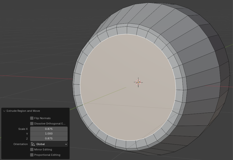
Scale: X: 0.875
       Z: 0.875
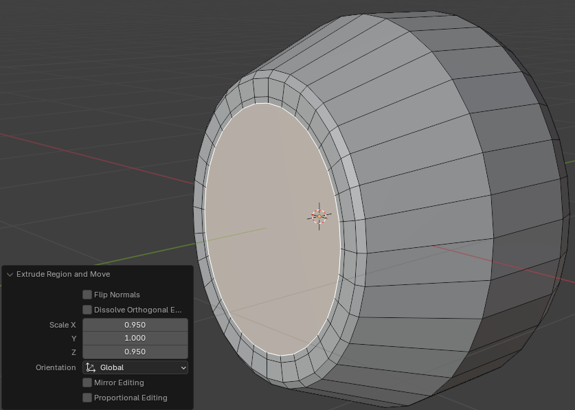
Scale X: 0.95
       Z: 0.95
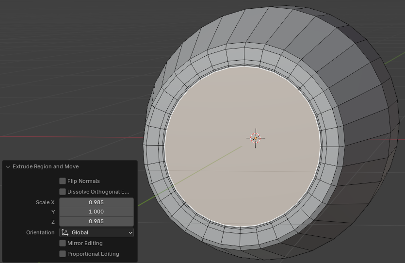
Scale: X: 0.985
       Z: 0.985
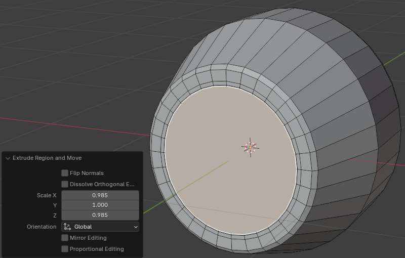
Scale: X: 0.985
       Z: 0.985
Scale: X: 0.95
       Z: 0.95
Move: X: 0
      Y: 0.25
      Z: 0
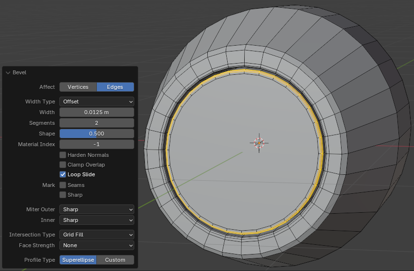
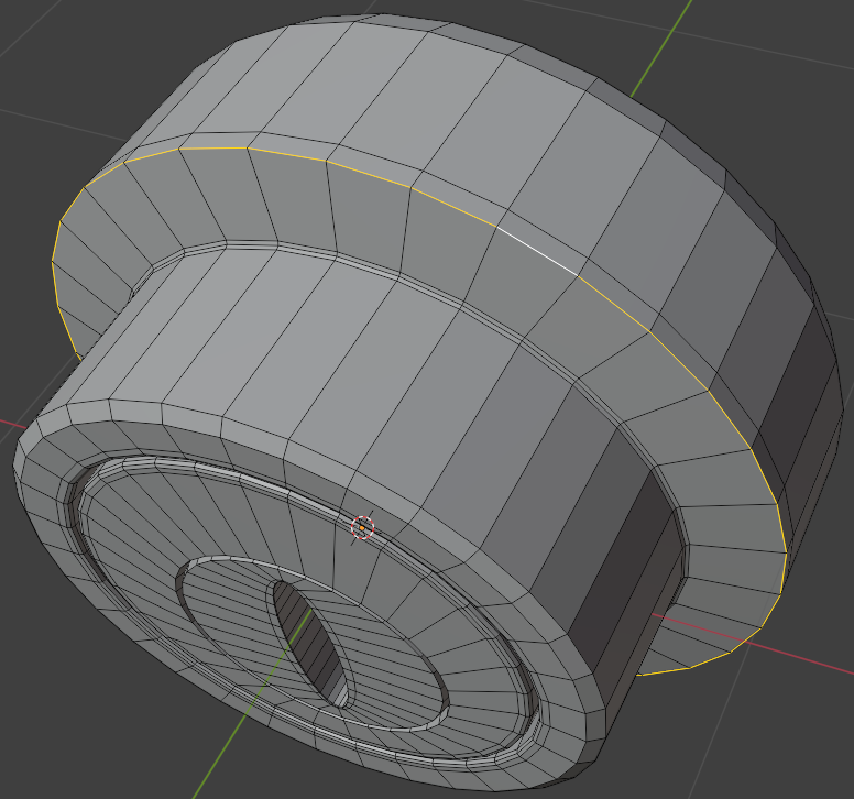
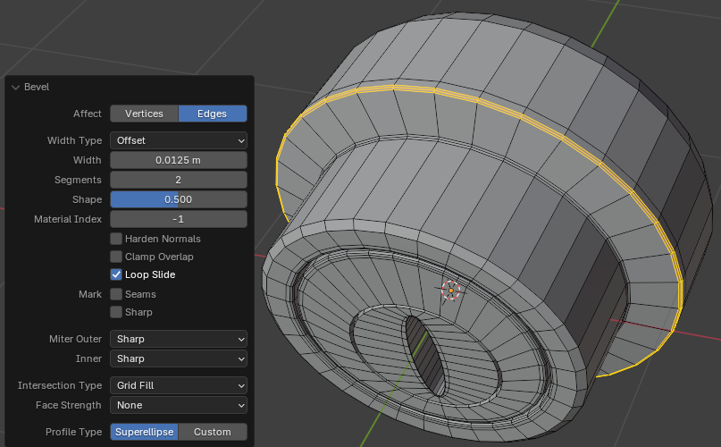
Width:    0.0125
Segments: 2
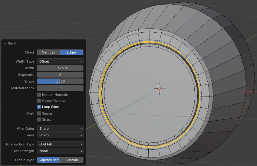
Width:    0.0125
Segments: 2
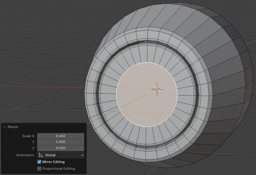
Scale X: 0.65
      Z: 0.65
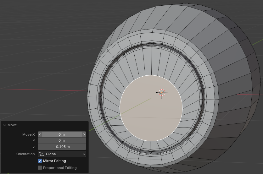
Move X: 0
          Y: 0
          Z: -0.105
Move X: 0.975
Z: 0.975Move X: 0.975
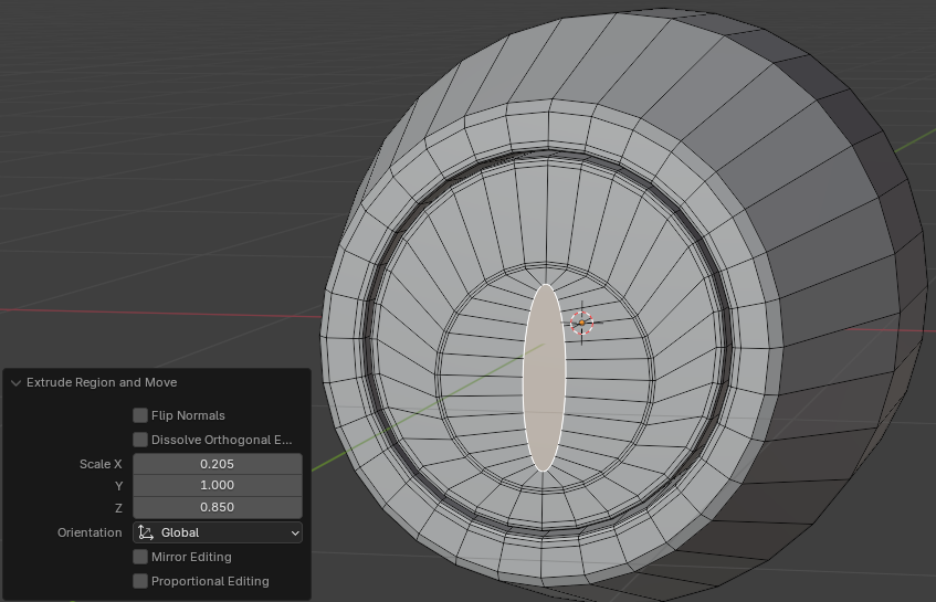
Z: 0.975Move X: 0.205
Z: 0.85
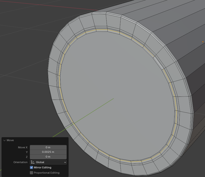
Move: X: 0
       Y: 0.025
       Z: 0
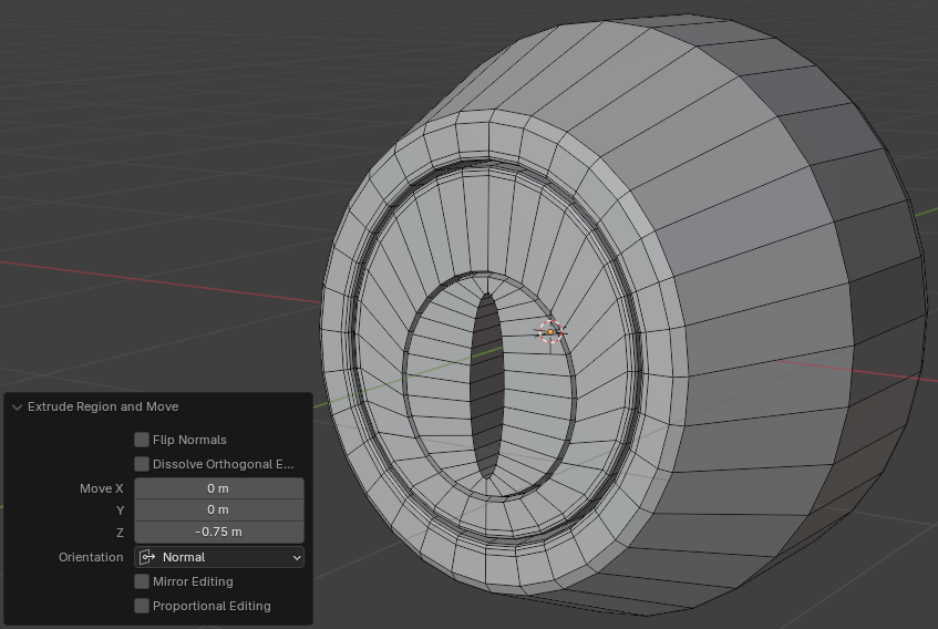
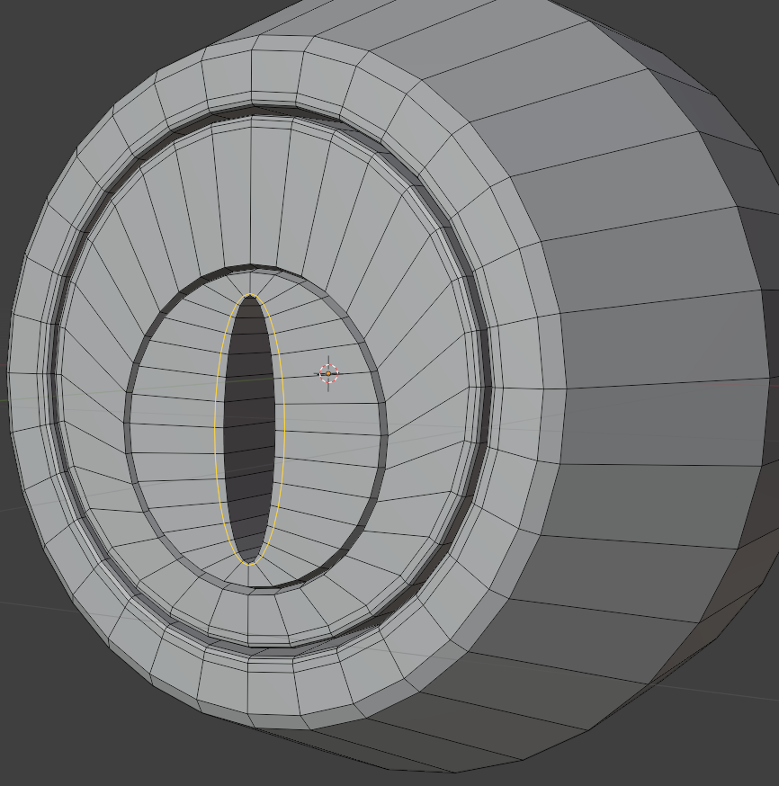
Move X:  0
     Y:  0
     Z: -0.75
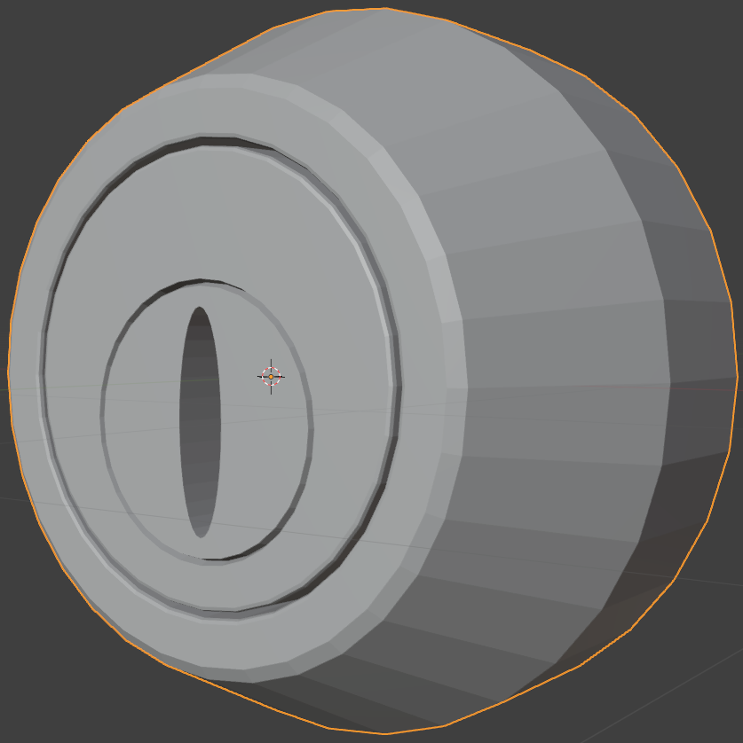
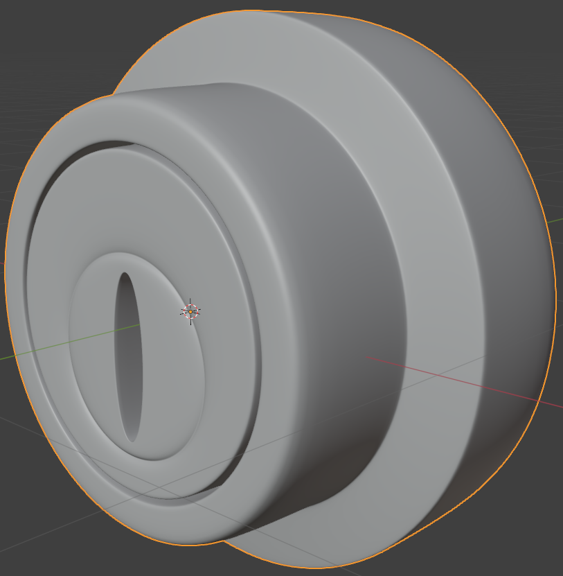
Levels Viewport: 2
Creating a Varying Lock
Door locks come in various designs. In this section, we will modify the design from the previous section.
![]() Practical Learning: Creating a Varying Lock
Practical Learning: Creating a Varying Lock
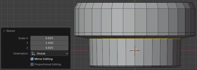
Scale X: 0.825
      Z: 0.825
Width:    0.0125
Segments: 2
Width:    0.0125
Segments: 2
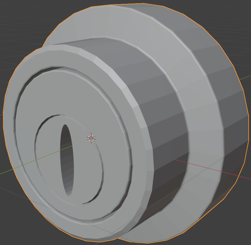
Levels Viewport: 2
|
|
|||
| Simple House | Copyright © 2016-2025, FunctionX | Monday 26 August 2024, 12:30 | External Door Handles |
|
|
|||