Modeling a House
.
Setting Up the House Body
.
 Practical Learning: Introducing the Model
- Save the following image to your computer:
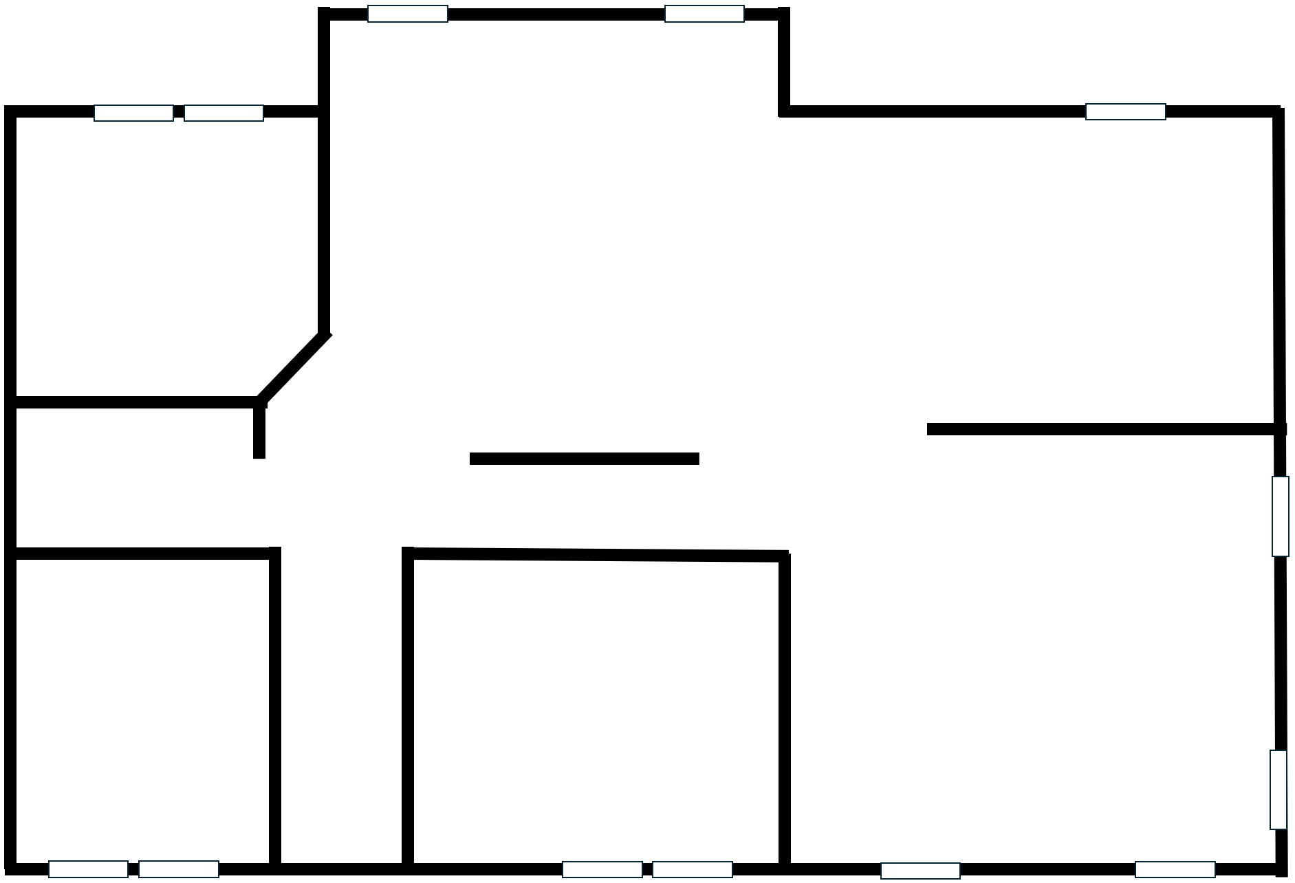
- Start Blender
- Click the default cube to select it (it should be selected already)
- In the Properties window, click the Object button
 (it should be selected already) to access the primary properties of the cube
- Change the name to HouseBody and press Enter
- In the Outliner, click the Hide In Viewport button of the HouseBody item to hide it
- Save the following image to your computer:
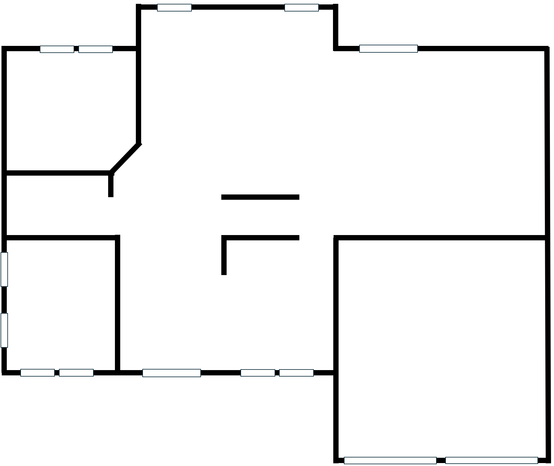
- Back in Blender, to change the view, on the top menu, click View -> Viewpoint -> Top
- To display an image, on the top menu, click Add -> Image -> Background...
- Locate and select the above image
- In the Outliner, click the Hide In Viewport button of the HouseBody item to unhide it
- On the 3D Viewport toolbar, click the Transform button

- In the Viewport, click the HouseBody cube to select it
- Click the Toggle X-Ray button
 to make the cube transparent
- Use the tools of the Tranforms button to enlarge the cube as follows (don't try to be too precise; this is not a professional architectural job):
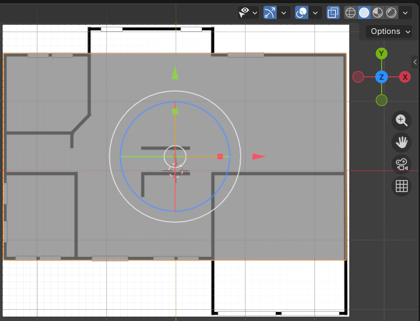
- On the 3D Viewport toolbar, click the Move button
 to make sure no modeling tool is selected
- In the Outliner, click the Hide In Viewport button of the HouseBody item to hide it
- Save the following image to your computer:
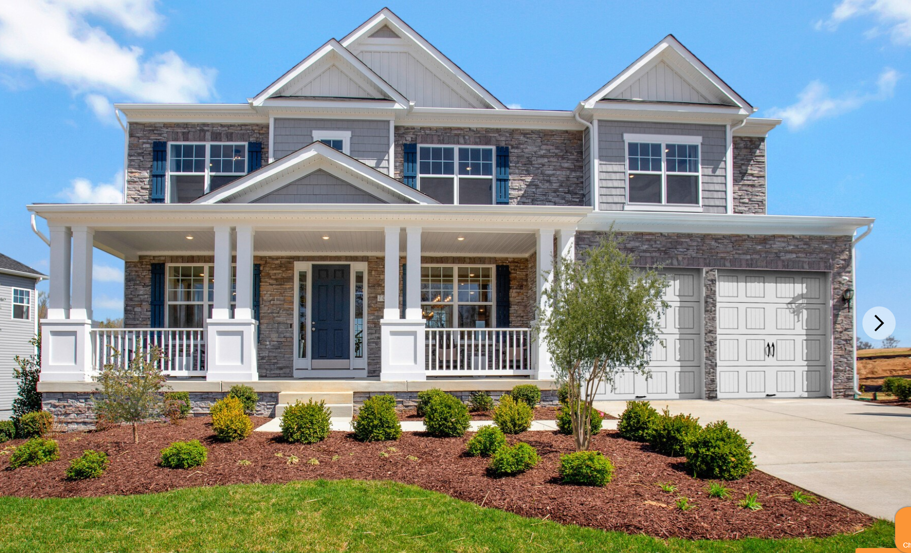
- Back in Blender, to change the view, on the top menu, click View -> Viewpoint -> Front
- To display an image, on the top menu, click Add -> Image -> Background...
- Locate and select the above image
- In the Outliner, click the Hide In Viewport button of the HouseBody item to unhide it
- On the 3D Viewport toolbar, click the background image you just added to select that image
- Use the S key and the tools of the Move button to enlarge and move the image as follows (don't be particularly precise; we are not performing a professional architectural project):
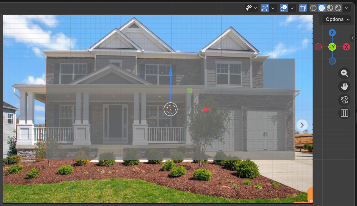
- Move the same image up so that its foundation aligns with the red line that represents the X axis (don't be particularly precise; we are not performing a professional architectural project)
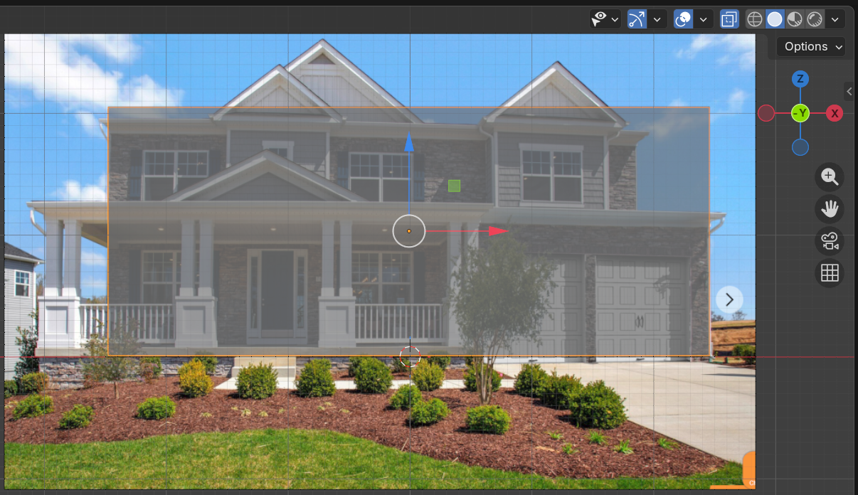
- On the 3D Viewport, click the HouseBody cube to select it
- Move the HouseBody cube up so that its bottom border aligns with the red line that represents the X axis (don't be particularly precise; we are not performing a professional architectural project):
- In the Outliner, click the Hide In Viewport button of the HouseBody item to hide it
Creating the Windows
 Practical Learning: Calling a Function
- To add a new object, on the top menu, click Add -> Mesh -> Cube
- On the 3D Viewport toolbar, click the Transform button
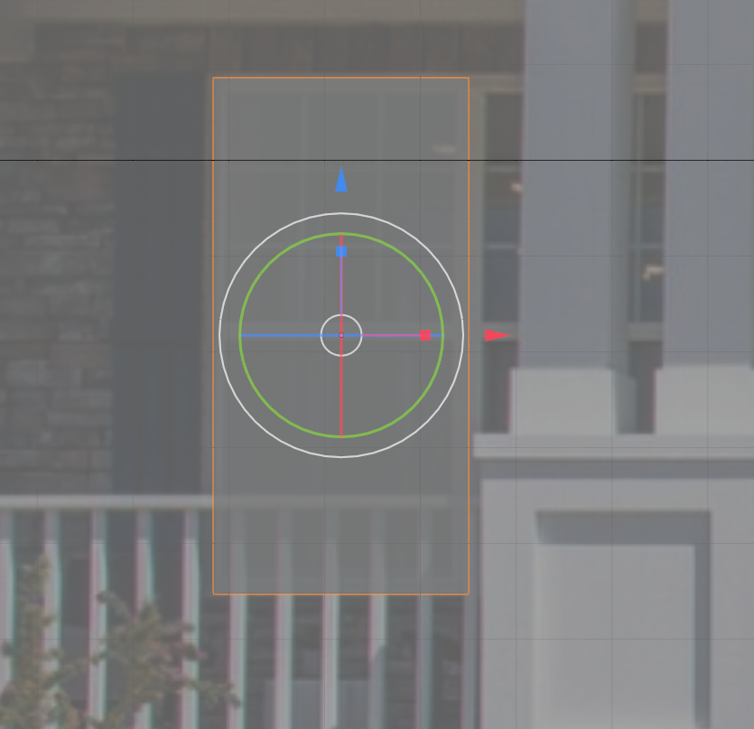
- Use S key and the tools of the Tranforms button to set the size of the cube to one left side of a window as follows:
- Back in Blender, to change the view, on the top menu, click View -> Viewpoint -> Top
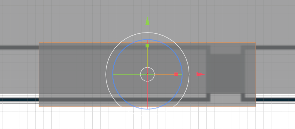
- Use S key and the tools of the Tranforms button to set the width of the cube to be a little wider than a wall as follows:
- Click the Toggle X-Ray button to remove the transparency
- Make sure the HouseBody cube is selected (if it is not, in the Outliner, click HouseBody).
On the top-main menu of Blender, click Modeling
- To display , position the mouse in the 3D Viewport. Press Shift + D and press Enter
- To display.
Change the following values:
Name:
Location: X: 0
          Y: 0.025
          Z: 1.355
Rotation: X: 90
          Y: 0
          Z: 0
Scale:    X: 2.6
          Y: 1.35
          Z: 0.025
In the left toolbar, click the Move button
-
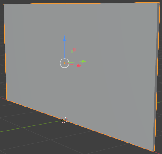
- In the Object section of the Properties window, change the Y location to 3.975
Name:       Wall-External-Back
Location Y: 3.975
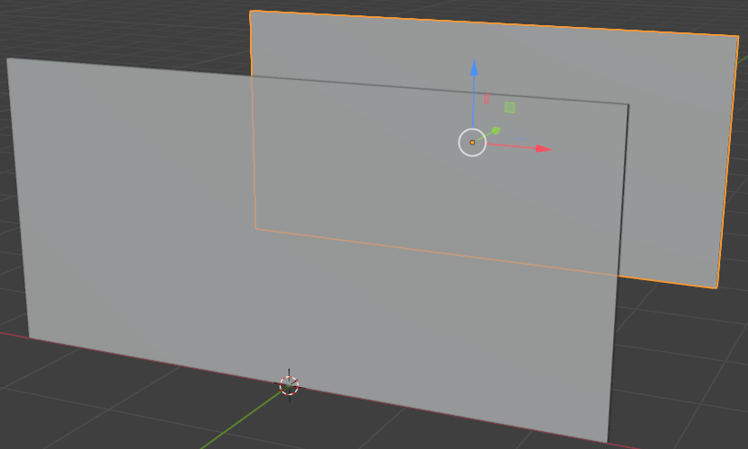
- In the Object section of the Properties window, change the following values:
Name:         Wall-External-Left
Location: X: -2.58
          Y:  2
          Z:  1.355
Rotation: X:  90
          Y:  0
          Z:  90
Scale:    X:  2
          Y:  1.35
          Z:  0.025
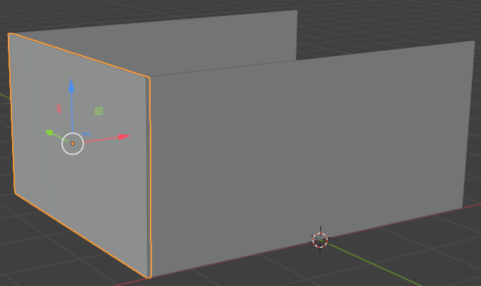
- To duplicate the wall, position the mouse in the 3D Viewport. Press Shift + D and press Enter
- In the Object section of the Properties window, remove the - sign in the value of the Y location
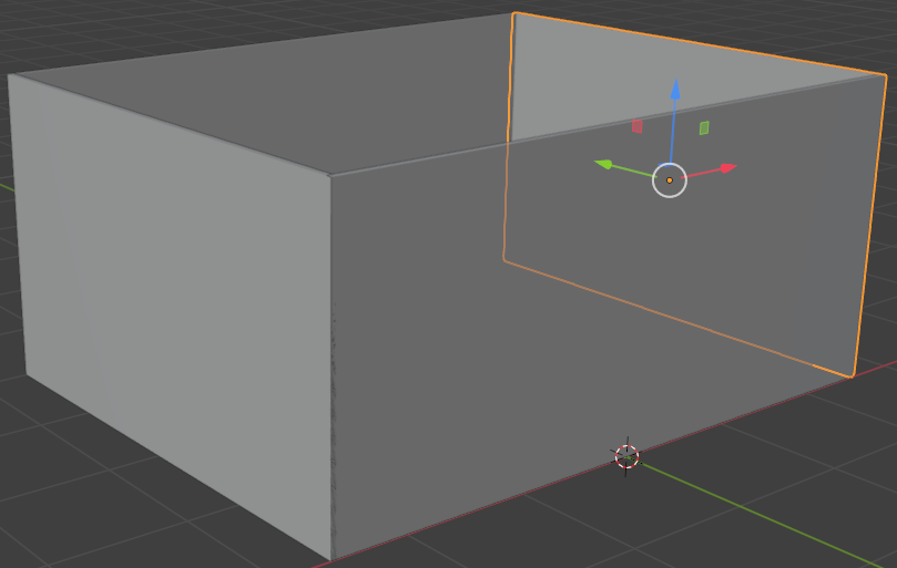
Name:       Wall-External-Right
Location X: 2.58
Adding the Entrance Door
Obviously, a house should have doors. In this section, we will add the necessary doors to our house.
Practical Learning: Adding an Entrance Door
- In a previous lesson, we modeled a simple door. Start another instance of Blender and open that file
- Draw a rectangle that touches the door frame and its inside face (the door leaf)
- Press Ctrl + C to copy the door to the clipboard
- Return to the instance of Blender where we are modeling the house
- Position the mouse in the 3D Viewport and press Ctrl + V to paste the door
- While the door is still selected, right-click anywhere in the 3D Viewport and click Move to Collection
- On the Move to New Collection dialog box, click Create
- On the top menu, click View -> Viewpoint -> Front
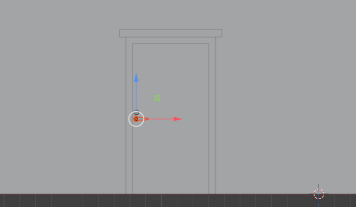
- Use the red arrow of the X axis to move the door to the left as follow:
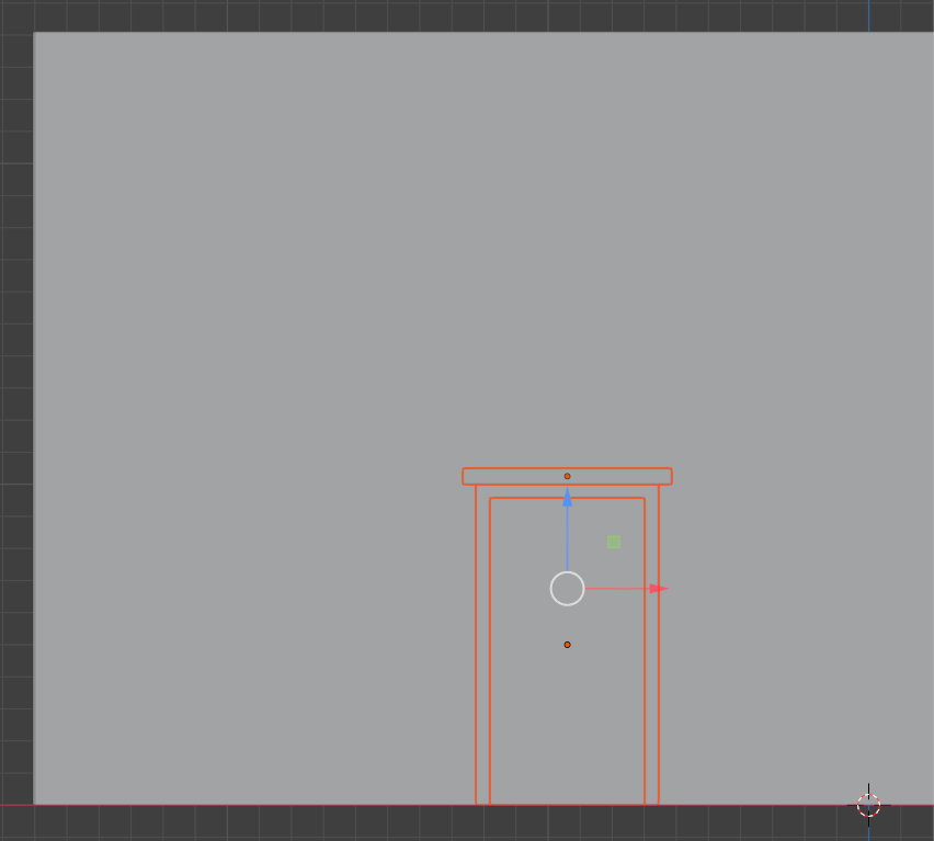
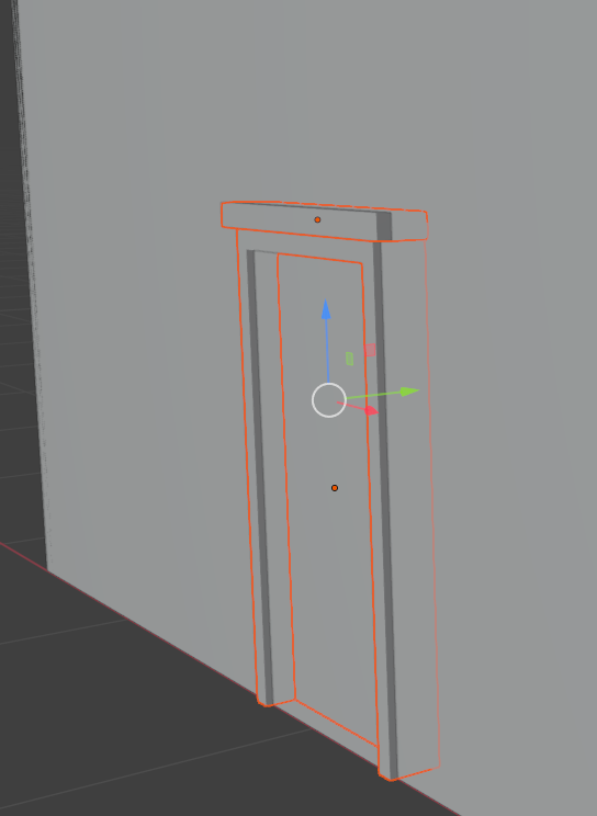
- In a previous lesson, we modeled a simple door lock. In the other instance of Blender you had started, open the file of that door lock
- Click the door lock to select it
- Press Ctrl + C to copy it
- Return to the instance of Blender where we are modeling the house
- Position the mouse in the 3D Viewport and press Ctrl + V to paste the door
- While the door lock is still selected, right-click anywhere in the 3D Viewport and click Move to Collection
- On the Move to Collection dialog box, click Door-External
- On the top menu, click View -> Viewpoint -> Front
- Use the red arrow of the X axis to move the door to the left as follow:
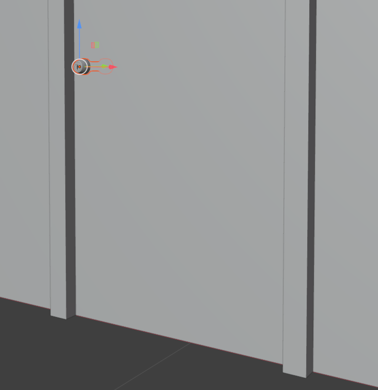
- In a previous lesson, we modeled a door handle. In the other instance of Blender you had started, open the file of that door lock
- Draw a rectangle that touches the parts of the door handle to select
- Press Ctrl + C to copy the selection
- Return to the instance of Blender where we are modeling the house
- Position the mouse in the 3D Viewport and press Ctrl + V to paste the door
- While the door handle is still selected, use the blue arrow of the Z axis to move the door handle and its lock down as follow:
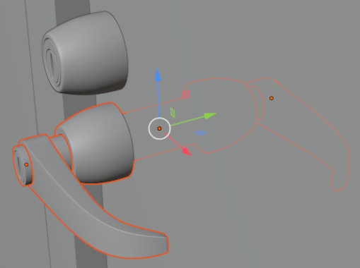
Adding a Kitchen Door
The house has a kichen and that kitchen will use an external door. In this section, we will add that door.
Practical Learning: Adding a Kitchen Door
- In the Outliner, click one of the objects in the Door-External node
- Press and hold Shift
- Still in the Outliner, click each one of the object objects in the Door-External node to select them
- On the top menu, click View -> Viewpoint -> Top
- Press Alt + D and press Enter
- To rotate the duplicated door, first press the R key
- Press Z to rotate horizontally
- Type 180 and press Enter
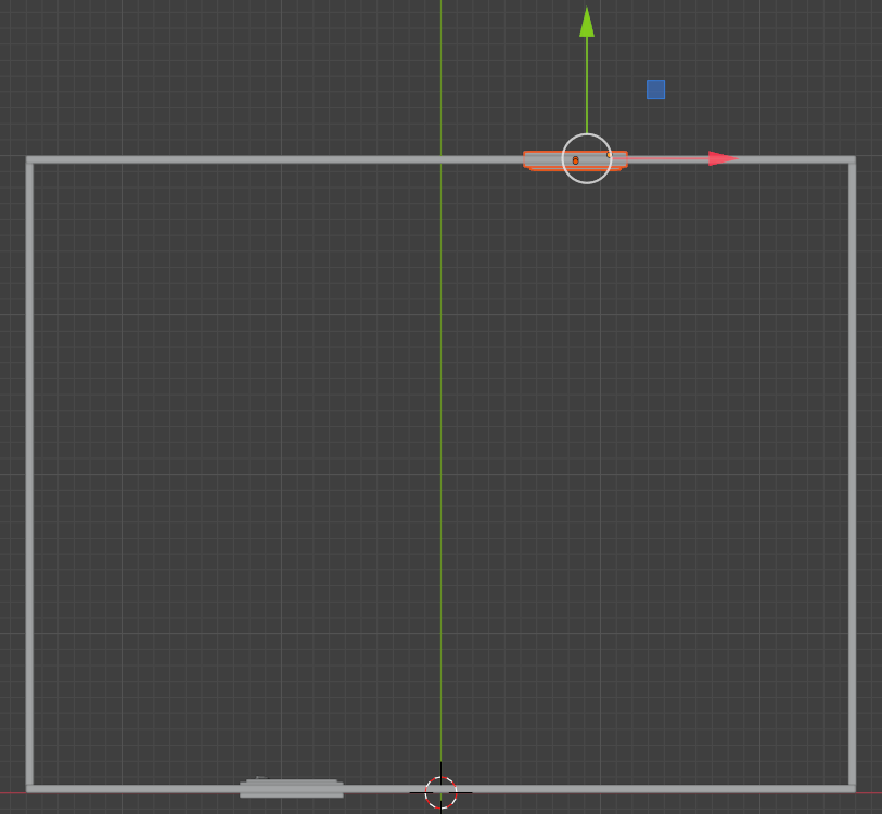
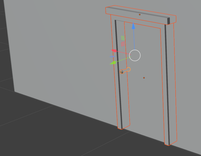
- While the door is still selected, move it to the back wall of the house as follows:
- On the top menu, click View -> Viewpoint -> Back
- While the door and its locks are still selected, press Alt + D and press Enter
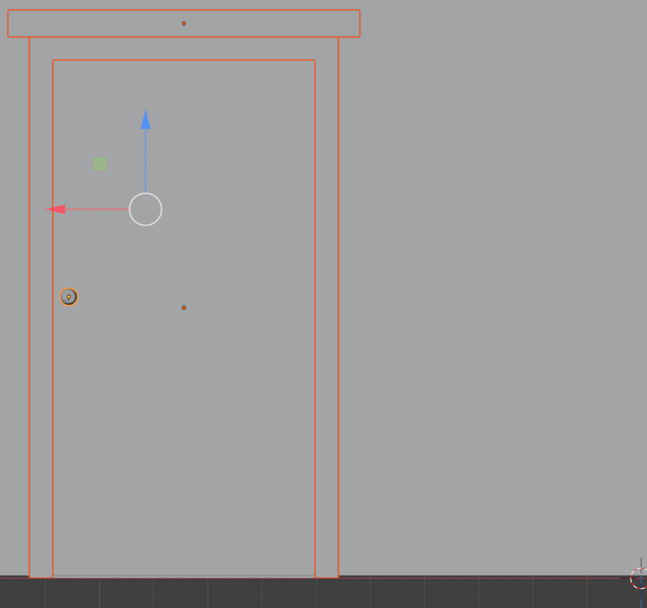
- Use the X arrow to move the duplicated door to the right side of the other back door
- Move the door lock and the handle to the right side of the door:
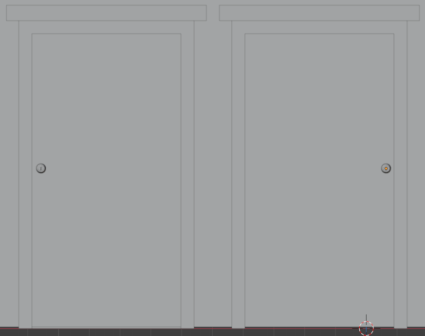
Adding a Garage Door
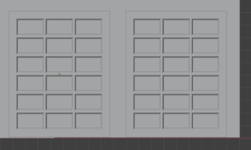
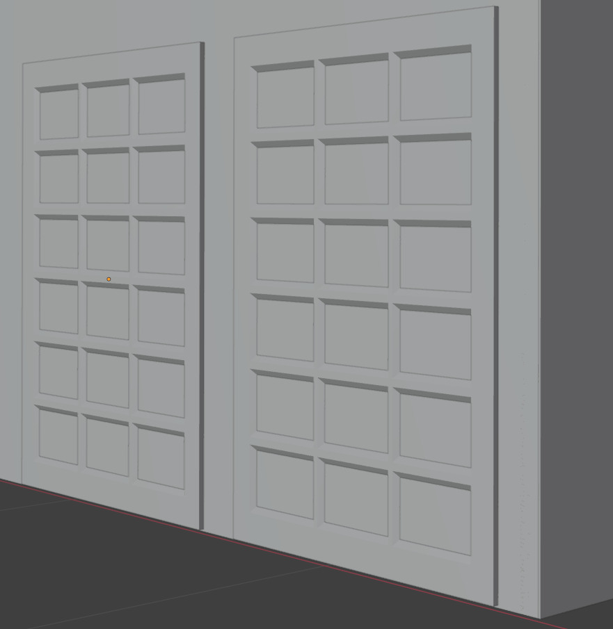
The house has an indoor garage. That garage has a door. We will make it a two-door garage. In this section, we will add those doors.
Practical Learning: Adding Two Garage Doors
- In a previous lesson, we modeled a garage door. In the other instance of Blender, open that file
- Click the garage door to select it
- Press Ctrl + C to copy the garage door to the clipboard
- Position the mouse in the 3D Viewport and press Ctrl + V to paste the door
- Position the garage doors to the right side of the house:
Adding a Large Window
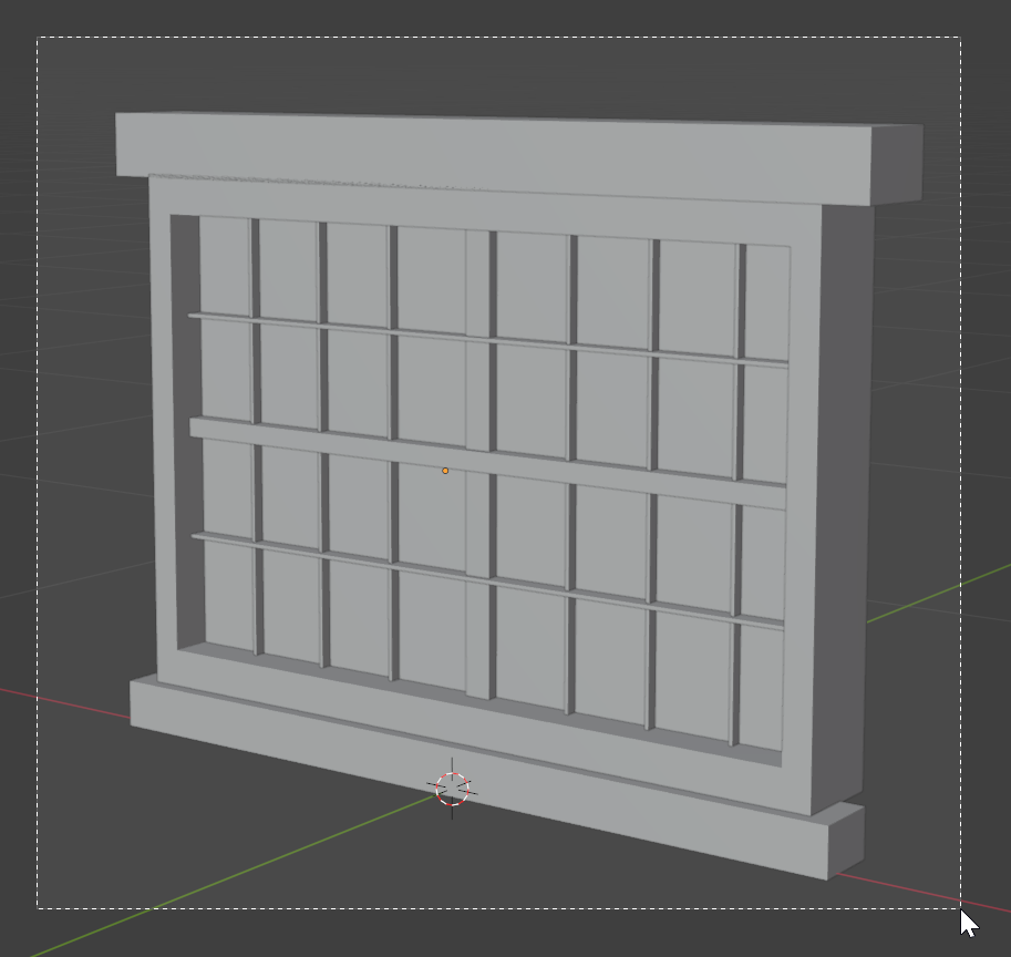
Obviously, the house has windows. Now, we will add some windows. We start with a large window because the house uses only one of them.
Practical Learning: Adding a Large Window
- In a previous lesson, we modeled a large window. In the other instance of Blender you had started, open the file of that door lock
- Draw a rectangle that touches the parts of the window to select
- Press Ctrl + C to copy the selection
- Return to the instance of Blender where we are modeling the house
- Position the mouse in the 3D Viewport and press Ctrl + V to paste the door
- While the window is still selected, use the visual arrows to move the window to the right side of the from door as follow:
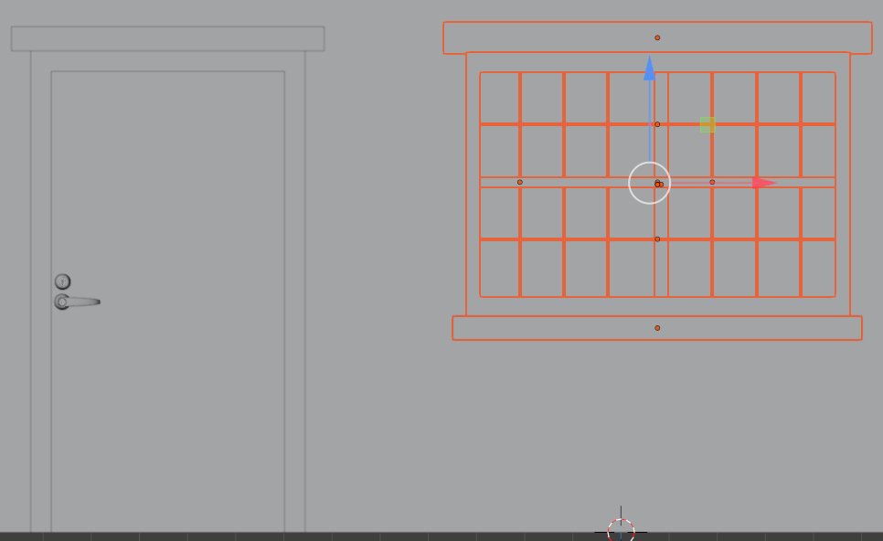
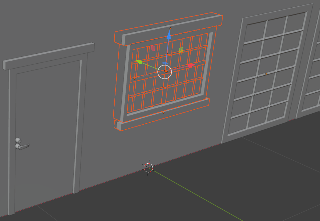
Adding Medium Windows
The house must use various windows for different rooms of the house. In this section, we will add one of those windows, and then duplicate it for the rooms that need such a window.
Practical Learning: Adding Windows
- In a previous lesson, we modeled a simple window. In the other instance of Blender, open that file
- Draw a rectangle to touches the parts of the window to select it
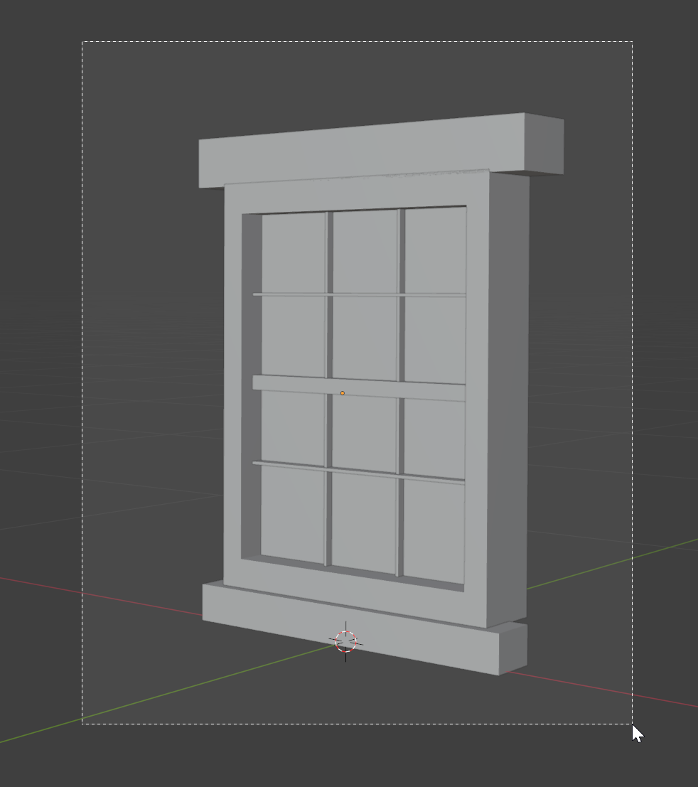
- Press Ctrl + C to copy it
- Return to the instance of Blender where we are modeling the house
- Position the mouse in the 3D Viewport and press Ctrl + V to paste the door
- While the window (and its parts) is still selected, right-click anywhere in the 3D Viewport and click Move to Collection
- On the Move to Collection dialog box, click New Collection
- Type Window-Front-BL
- Click Create
- On the top menu, click View -> Viewpoint -> Front
- Use the visual arrows in the 3D Viewport to move the window to the left of the front door as follow:
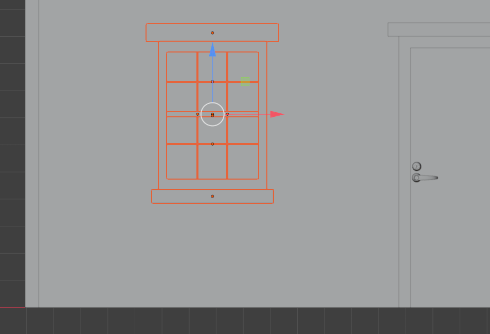
- Make sure the window is selected (if it is not, in the Outliner window, click the first item below Window-Front-BL; press and hold Shift; click the last item below Window-Front-BL to select the whole window; then release Shift).
Press Alt + D to duplicate the window
- While the window and all its parts are still selected, to change the orientation of the window, press R (to rotate)
- Press Z to rotate vertically
Type -90 and press Enter |
- Use the visual X (red) and Y (green) but not the Z (blue) arrows on the screen to position the window to the right section of the left wall
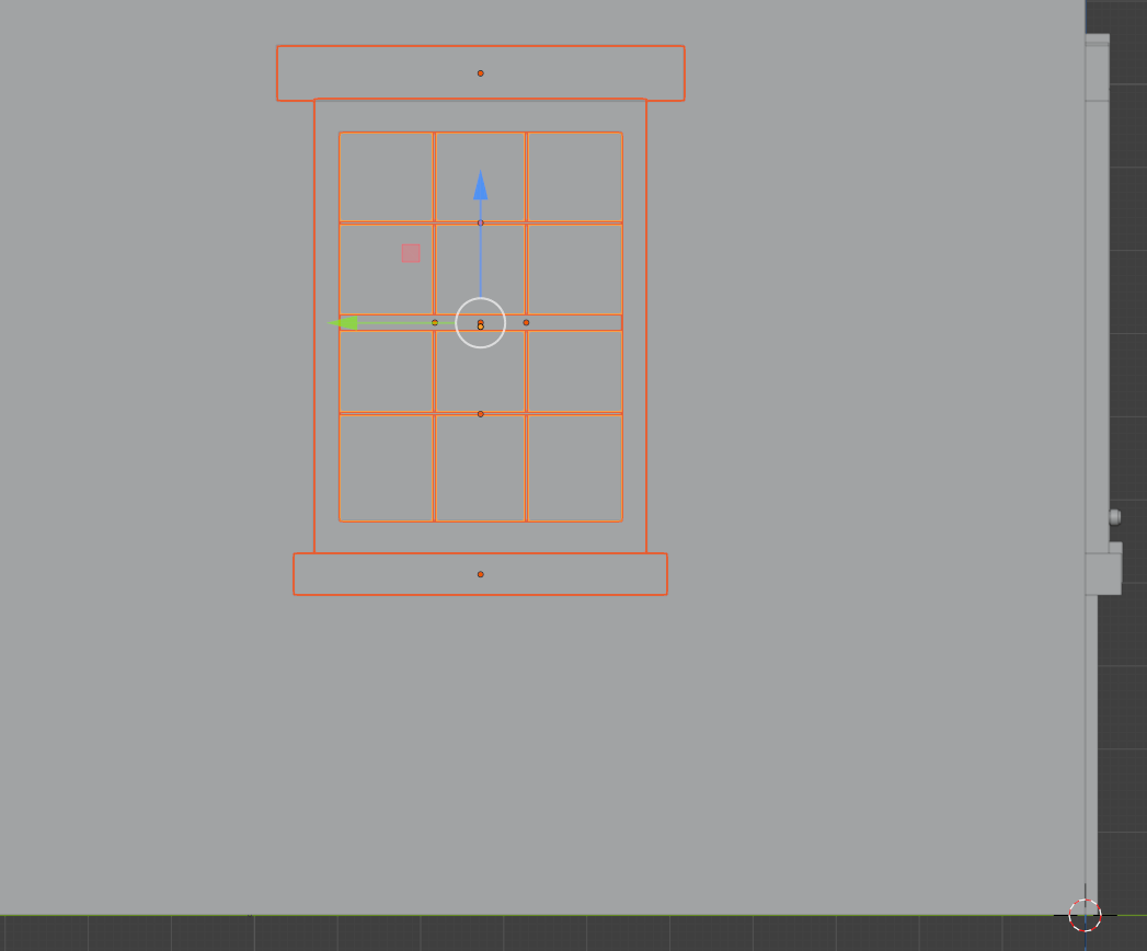
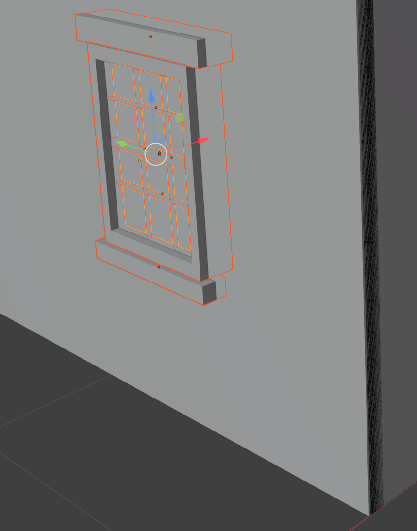
- While the window (and its parts) is still selected, right-click anywhere in the 3D Viewport and click Move to Collection
- On the Move to Collection dialog box, click New Collection
- Type Window-Left-Wall-BR
- Click Create
- Position the mouse in the 3D Viewport, press Alt + D to duplicate and move the duplicate
- While the window (and its parts) is still selected, right-click anywhere in the 3D Viewport and click Move to Collection
- On the Move to Collection dialog box, click New Collection
- Type Window-Left-Wall-BL
- Click Create
- Move the new window to the left side of the back wall as follows:
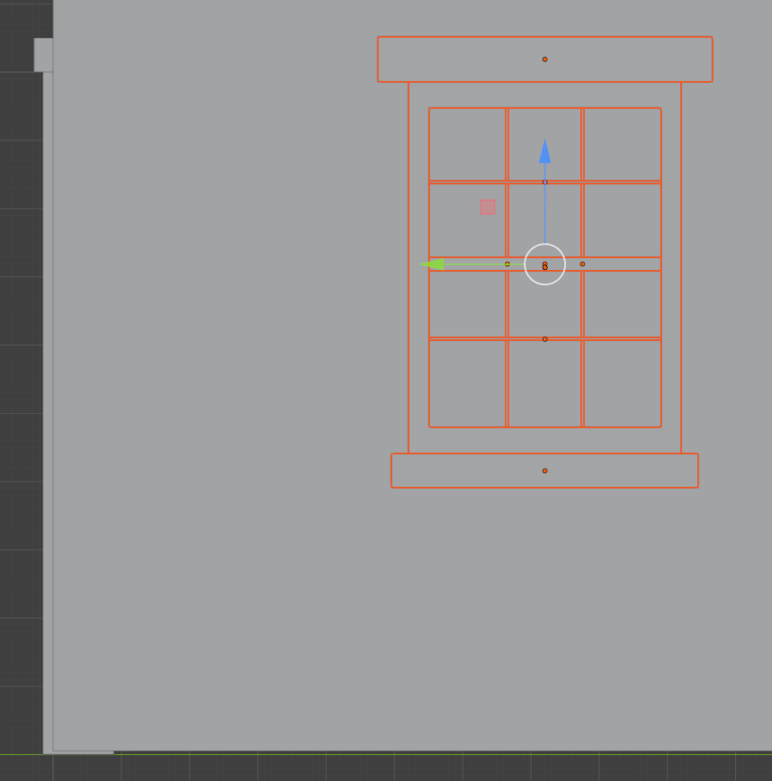
- To select both left wall windows, in the Outliner, select all objects in the Window-Front-BL section and those in the Window-Left-Wall-BL section:
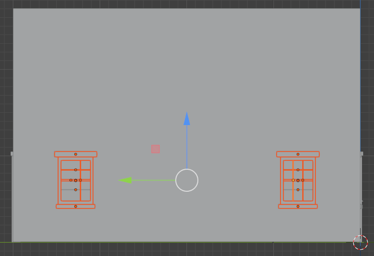
- To duplicate the windows, press Alt + D and press Enter
- Move the selected window up as follows:
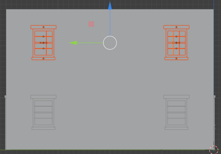
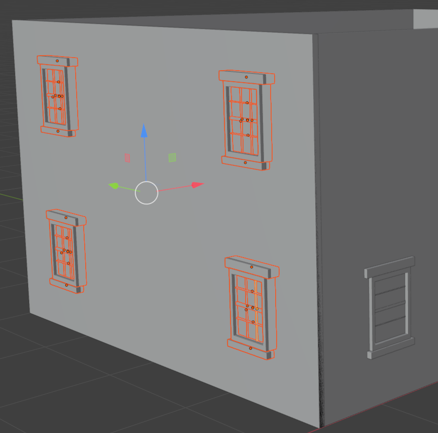
- Use any of the above techniques to add four new windows to the front wall of the house as follows:
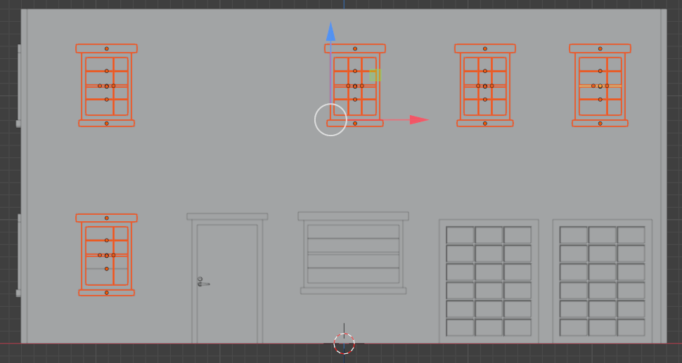
- In the same way, add two windows to the bottom-right section of the right was as follows:
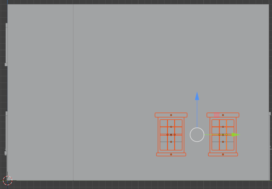
- In the same way, add four windows to the back door as follows:
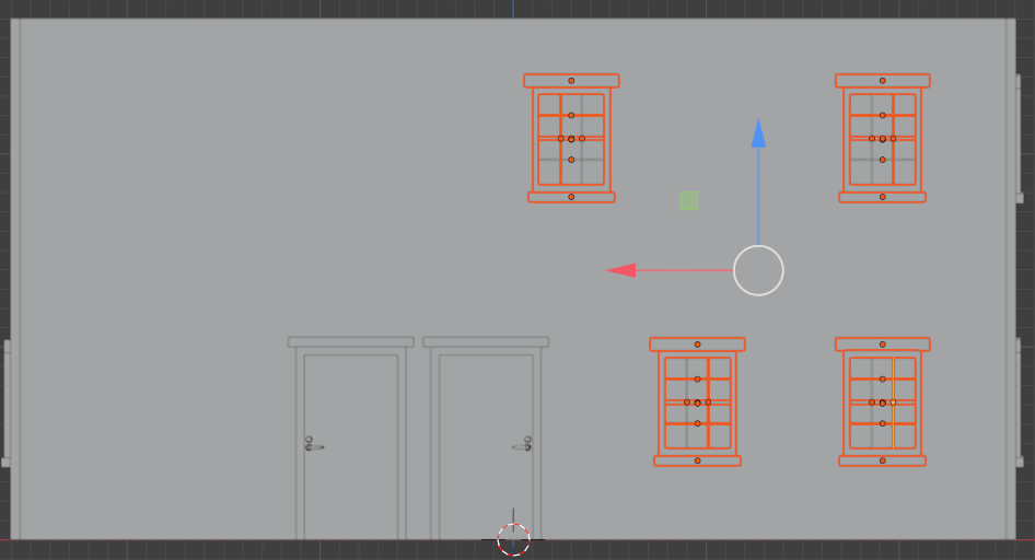
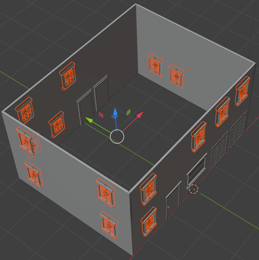
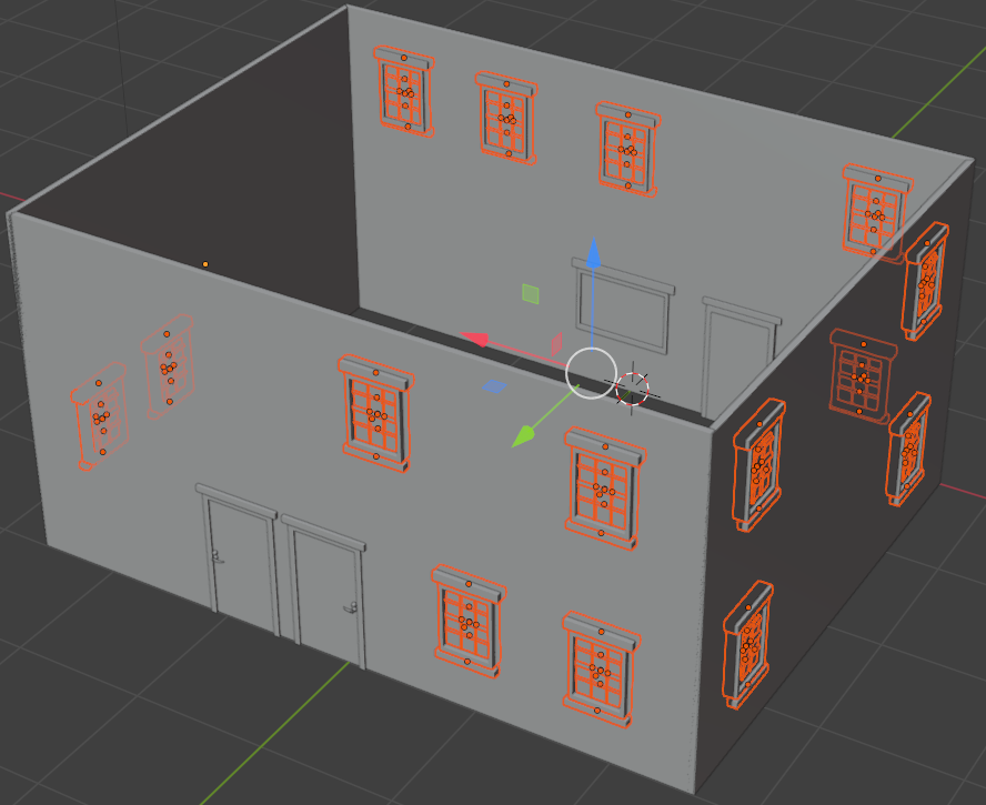
Doors and Windows Openings
In previous sections, we add windows by their positions. Now we will create some openings on the walls where the windows and doos are positioned.
Practical Learning: Creating Openings for Doors and Windows
- Click an empty area of house to select the front wall
- Position the mouse as close as possible to the left (or the right) border of the wall. Press Ctrl + R to create a horizontal cut and click once
- Move the cut to position it within the top border of the top windows:
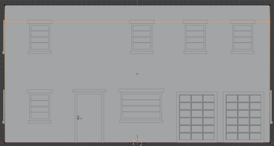
- Click to confirm the loop cut
- In the same way, create horzontal cuts within the bottom borders of the top window, within the top borders of the bottom window, within the bottom borders of the bottom window, and within the top borders of the garage window:
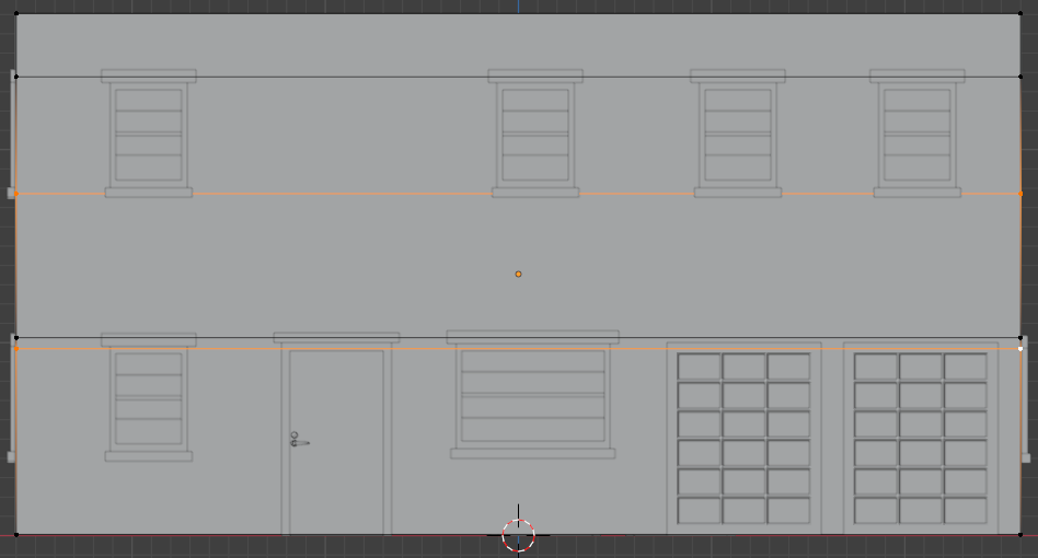
- Position the mouse as close as possible to the top (or the bottom) border of the wall of the house. Press Ctrl + R to create a vertical cut and click once
- Move the cut to position it within the left border of the left windows:
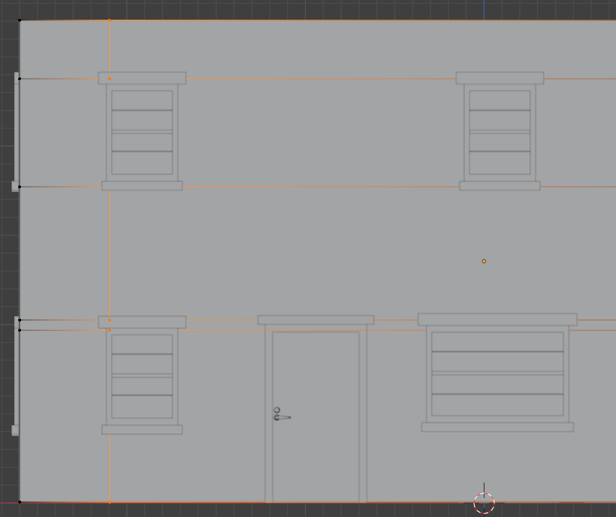
- Click to confirm the loop cut
- In the same way, create horzontal cuts within the vertical borders of the windows and walls:
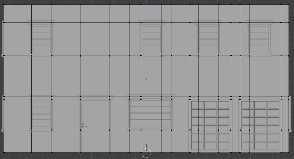
- On the top bar, click the Face button

- Click within a window or a door to select its inside face:
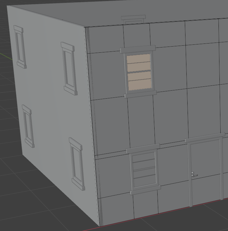
- Press Delete
- On the menu the comes up, click Faces. In the same way, delete the faces within windows and doors
- Rotate the house to access its inside. Delete the faces within windows and doors
- On the main menu of Blender, click Layout:
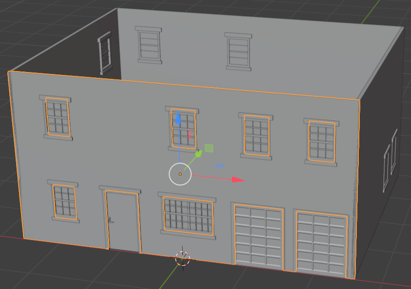
- Follow the above steps to create openings in the left wall:

- And delete the face(s) within each window:
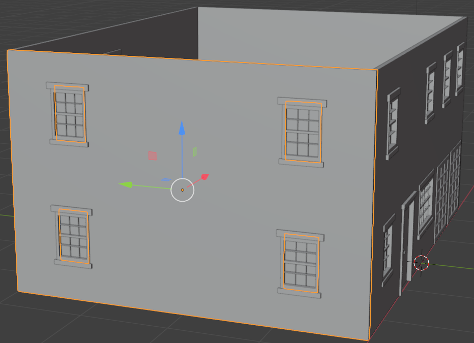
- In the same way, Follow the above steps to create openings in the back wall and delete the face(s) within each window
- On the top menu of Blender, click Layout
- To save the model, on the main menu of Blender, click File and click Save
- In the top combo box, specify a folder of your choice
- Change the file name to House-Medium
- Click Save Blender File
Modeling the Ceiling Frame
A house must be covered. That cover starts with a frame made of different parts, usually in wood. Since this is not an extended design, we will keep the ceiling frame to a minimum.
Practical Learning: Modeling the Ceiling Frame
- To start a ceiling, on the 3D Viewport menu, click Add -> Mesh -> Plan
- In the Object section of the Properties window, change the following values:
Name:         Ceiling
Location: X:  0
          Y:  2
          Z:  2.7

Scale:    X:  3
          Y:  2.265
          Z:  0
- Make sure the new plane is selected:

On the top menu, click Modeling
- Make sure you can access the top face of the new cube.
Press Ctrl + R to create a horizontal loop
- Move the mouse so the loop line would be paralle to the longer edges:

- Click once to create the loop and right-click to accept the loop:

- Press G to move the loop cut
- Press Z to move the loop cut vertically
- Move the mouse slightly and click
- In the bottom-left section of Blender, click Move to expand the window
- In the Move window, change the Z value to 1.275:
Move X: 0
     Y: 0
     Z: 1.275
- Position the mouse in the viewport. Then press A to select the faces
- Press E to extrude
- Move the mouse up slighly and click
- In the Extrude Region and Move window, change the Z value to 0.1:
Move X: 0
     Y: 0
     Z: 0.1
- On the 3D Viewport toolbar, click the Edge button

- Click the lower edge of one of the top faces:

- On the menu of the 3D Viewport, click View -> Viewpoint -> Right

- While the edge is selected, move the mouse slighty:

- Use the same steps to move the other edge:

- Make sure the mouse is positioned on the house.
Press M

- In the Asset Library window, drag the selected items and drop the group in the 3D Viewport
- Close Blender
- When asked whether you want to save, click Don't Save
Setting the Materials for Walls
We are planning to create some variances of the same house. Those variances will have different colors or wall appearances.
Practical Learning: Setting the Materials for Walls
- To access the materials of the faces, on the top-main menu of Blender, click Shading
- On the top menu, click View -> Viewpoint -> Front
- Click somewhere on the wall to select it
- Rotate the house to view it in perspective
- On the bottom bar, click Material to select it
- Type Large-Wall and press Enter
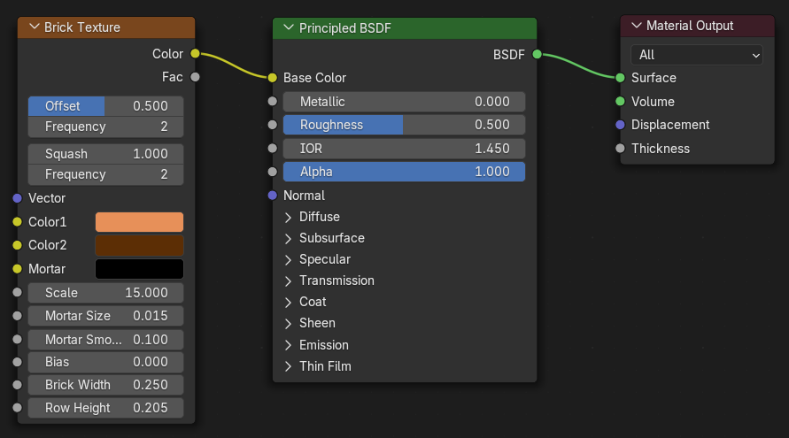
- On the Shading toolbar, click Add -> Texture -> Brick Texture
- From the Brick Texture window, drag Color and drop it to the Base Color of Principled BSDF
- In the Brick Texture window, change the following values:
Color 1:       #E79059FF
Color 2:       #5C2E05FF
Scale:         15
Mortar Size:   0.015
Mortar Smooth: 0.1
Brick Width:   0.25
Row Height:    0.205
- Click one of the smaller walls of the house to select it
- On the Shading toolbar, click the New Material button

- Type Small-Wall and press Enter
- On the Shading toolbar, click Add -> Texture -> Brick Texture
- From the Brick Texture window, drag Color and drop it to the Base Color of Principled BSDF
- In the Brick Texture window, change the following values:
Color 1:       #E79059FF
Color 2:       #5C2E05FF
Scale:         15
Mortar Size:   0.015
Mortar Smooth: 0.1
Brick Width:   0.295
Row Height:    0.205
- Click the other small wall to select it
- On the Shading toolbar, click the arrow of the Material button and select Small-Wall
- On the top-main menu of Blender, click Layout
- On the bottom bar, click the arrow of the Browse Material combo box
 and select Short-Wall
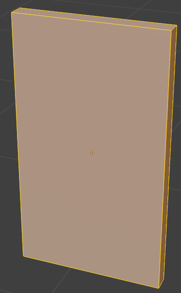
- To hide the walls of the house, in the numeric pad of the keyboard, press /
- On the left bar, click the Loop Cut button

- In the Resize window in the bottom-left section of the 3D Viewport window, change the following values:
Move: X: 2.55
      Y: 1
      Z: 1
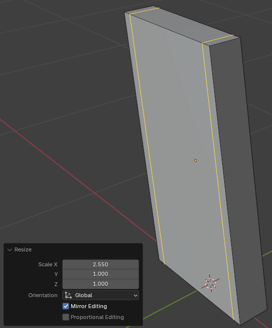
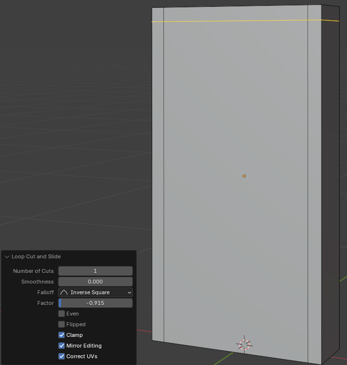
- On the top bar, click the Face button
- On the menu that appears, click Faces
- To display the hidden objects, in the numeric pad of the keyboard, press /
- To confirm the separated parts, on the top-main menu of Blender, click Layout
- Position the mouse on the 3D Viewport. On your keyboard, press H to hide the face
- Click any border of the window to select it
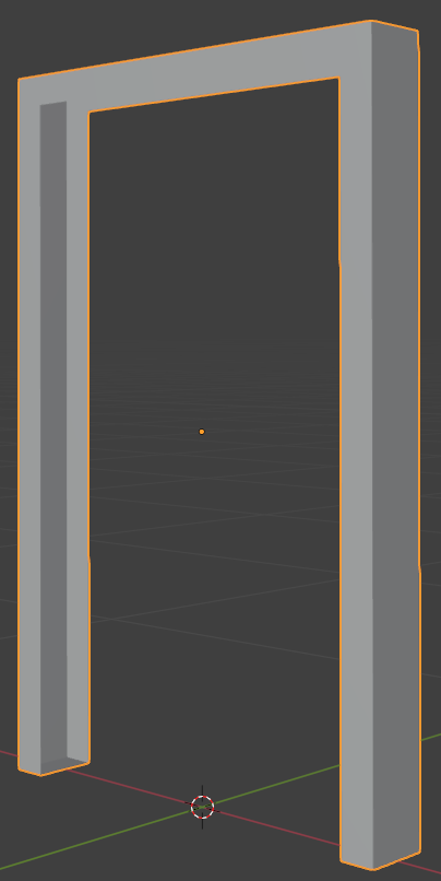
- To continue editing the door, on the main menu of Blender, click Modeling
- On the top bar, click the Edge button
- On the window, click one of the interior edges of the opening to select it
- On your keyboard, press and hold Shift
- Click each of the interior edges of both openings of the door but don't select the bottom edge of each side
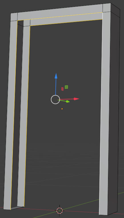
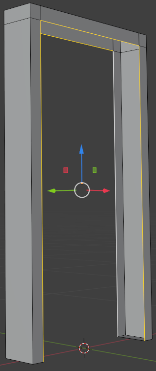
- On the menu bar, click Edge -> Bridge Edge Loops
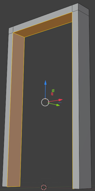
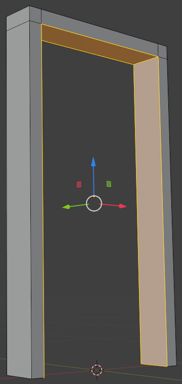
- On the top-main menu of Blender, click Layout
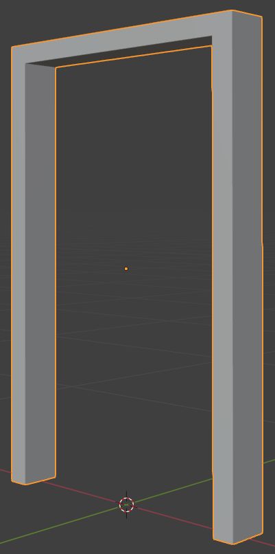
- In the 3D Viewport, click that interior face (Door-Leaf) to select it
- To edit the face, on the main menu of Blender, click Modeling
- On the top menu bar, click the Face button
- Click the large face on the door
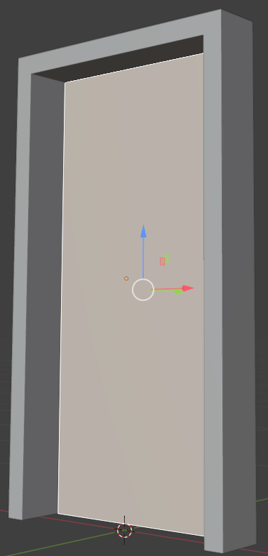
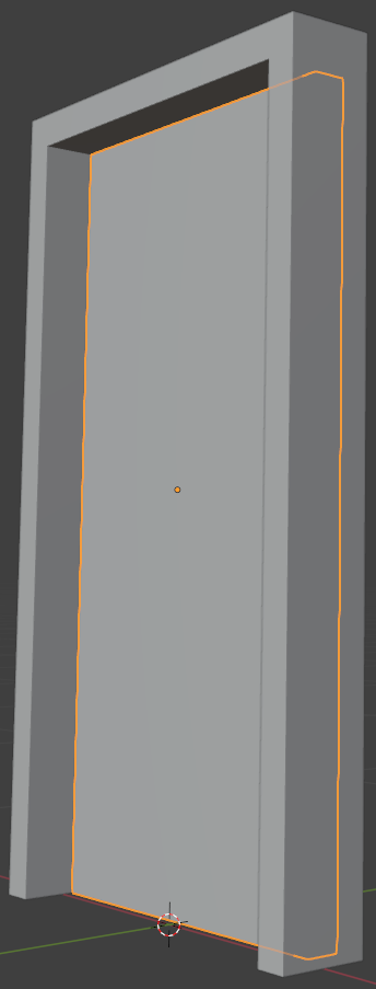
- Press E to extrude and press Enter
- On the main menu of Blender, click Layout

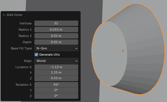
- In the Add Cube window, change the following characteristics:
Radius:     0.015
Radius 2:    0.01
Depth:       0.01
Location X: -1.135
         Y:  2.25
         Z:  0.55
Rotation X:  90
- Type as the name and press Enter
- To edit the cone, on the top-main menu of Blender, click Modeling
- To hide the other objects, in the numeric pad of the keyboard, press /
- Click and drag the Rotate button to see the large back face of the cone
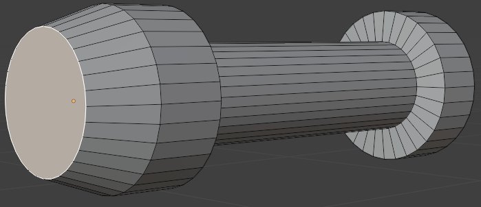
- On the top menu, click the Face button
- Click the large vertical face to select it
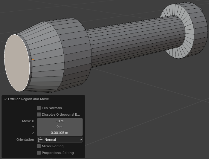
- Press E to extrude and press Enter
- In the Extrude Region and Move window, change the Z value to 0.45:
Move Z: 0.035
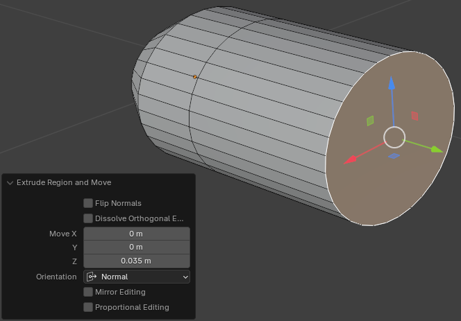
- Position the mouse on an empty area of the 3D Viewport window. Press E to extrude and press Enter
- In the Extrude Region and Move window, change the Z value to 0.1:
Move Z: 0.1
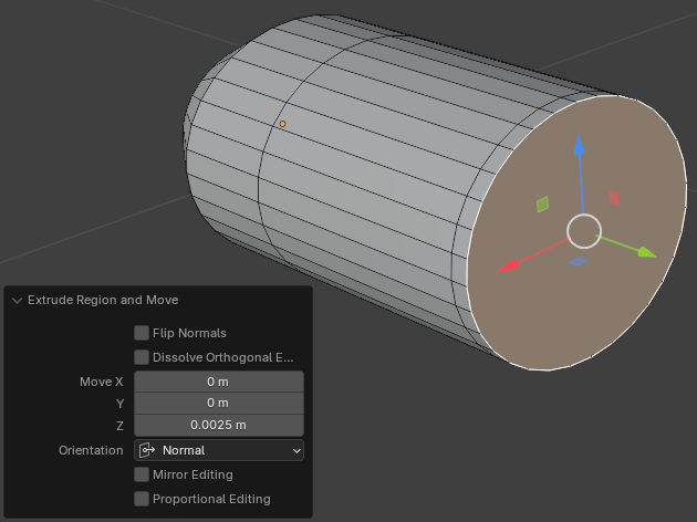
- Position the mouse in the 3D Viewport. Press S to resize the face. Pull the mouse slightly and click
- In the Resize window, change the X and the Z values to 0.95 each:
Scale: X: 0.95
       Z: 0.95
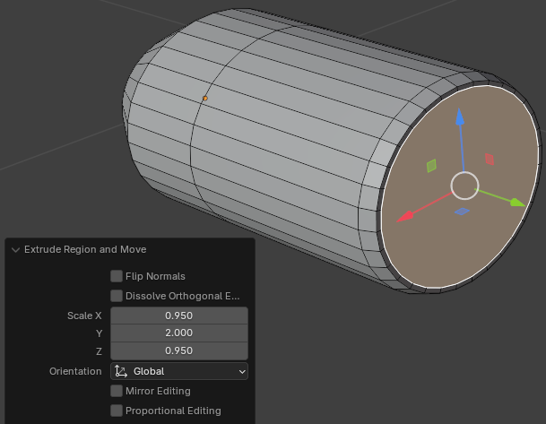
- Position the mouse in the 3D Viewport. Press E to extrude, then press S to resize, then press Enter
- In the Extrude Region and Move window, change the X and the Z values to 0.5:
Scale: X: 0.95
       Z: 0.95
- Rotate the cone to see the front face (you can use the middle button of the mouse)
- Click the front vertical face to select it
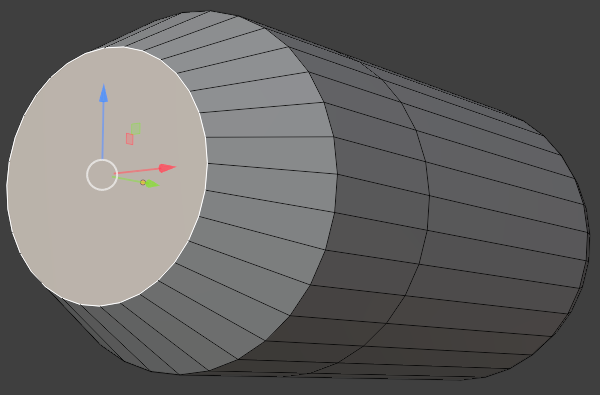
- Press E to extrude and press Enter
- In the Extrude Region and Move window, change the Z value to 0.025:
Move Z: 0.025
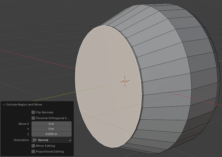
- Position the mouse in the 3D Viewport. Press S to resize. Slightly move the mouse and click
- In the Resize window, change the X and the Z values to 0.95 each:
Scale: X: 0.95
       Z: 0.95
- While the face is still selected, position the mouse in the 3D Viewport. Press E to extrude, then press S to resize, then press Enter
- In the Extrude Region and Move window, change the X and the Z values to 0.875:
Scale: X: 0.875
       Z: 0.875
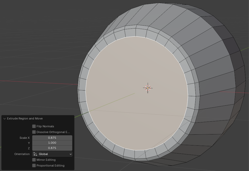
- While the face is still selected, position the mouse in the 3D Viewport. Press E to extrude, then press S to resize, then press Enter
- In the Extrude Region and Move window, change the X and the Z values to 0.95:
Scale X: 0.95
       Z: 0.95
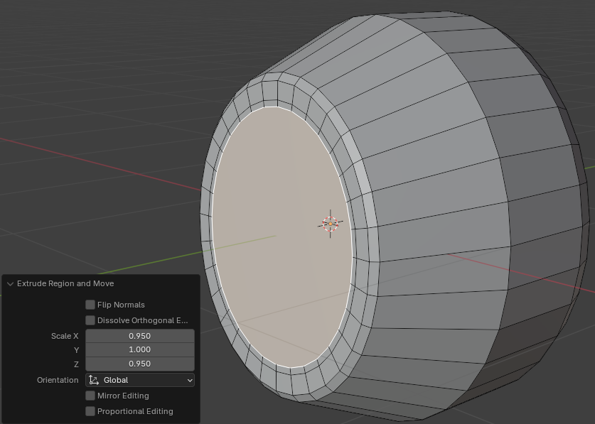
- While the face is still selected, position the mouse on the 3D Viewport window. Press E to extrude, then press S to resize, then press Enter
- In the Extrude Region and Move window, change the X and the Z values to 0.95 each:
Scale: X: 0.985
       Z: 0.985
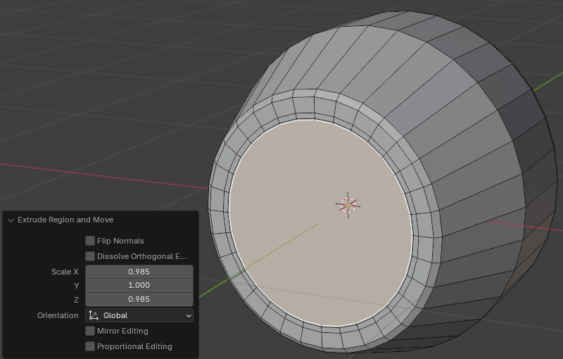
- While the face is still selected, position the mouse on an empty area of the 3D Viewport window. Press E to extrude, then press S to resize, then press Enter
- In the Extrude Region and Move window, change the X and the Z values to 0.95 each:
Scale: X: 0.985
       Z: 0.985
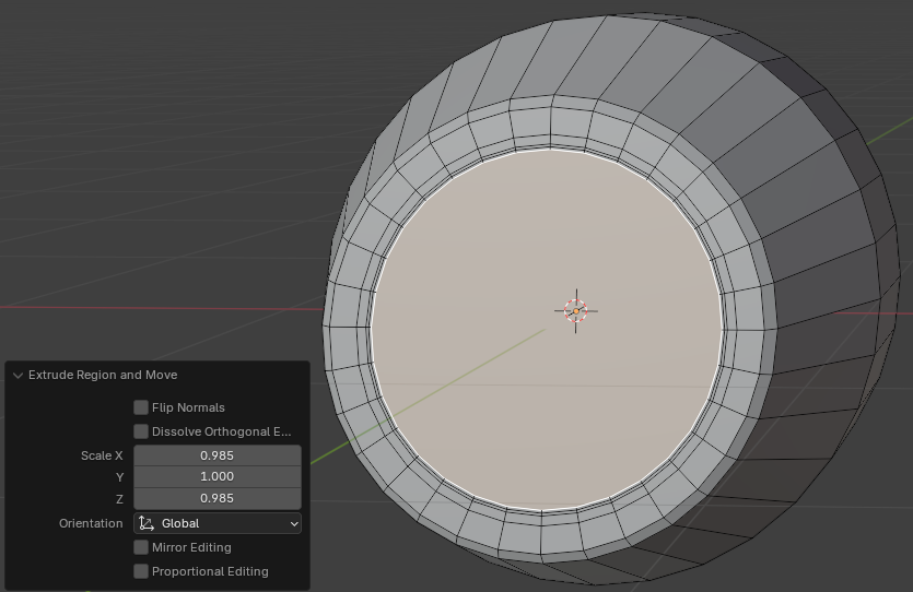
- While the face is still selected, position the mouse on an empty area of the 3D Viewport window. Press E to extrude, then press S to resize, then press Enter
- In the Extrude Region and Move window, change the X and the Z values to 0.95 each:
Scale: X: 0.95
       Z: 0.95
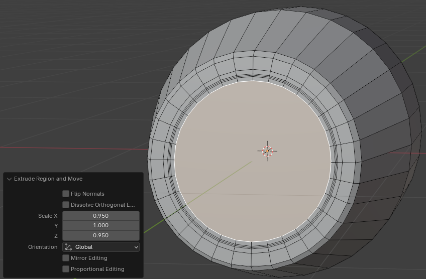
- On the top tool menu, click the Edge button
- Press and hold Alt
- On the shape in the 3D Viewport, click one of the edges of the 5th circle from the external circle
- Release Alt
- Press G slightly and click
- In the Move window, change the values as follows:
Move: X: 0
      Y: 0.25
      Z: 0
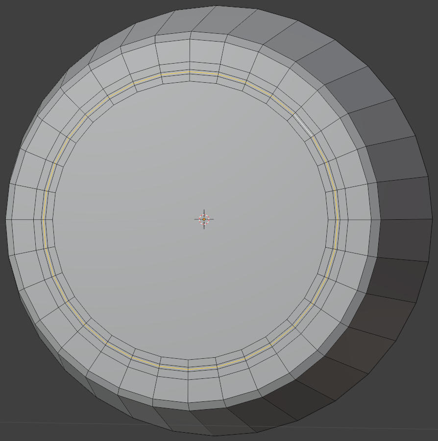
- Press and hold Alt
- Click one of the edges of the 4th circle from the external circle
- Release Alt
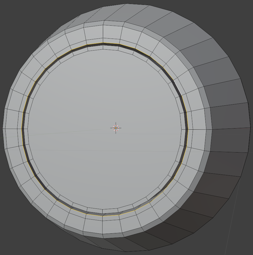
- Press Ctrl + B and press Enter
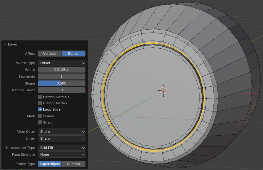
- In the Bevel window, change the following values:
Width:    0.0125
Segments: 2
- While the Edge option is still selected, press and hold Alt
- Click one of the edges outside the inner circle
- Release Alt
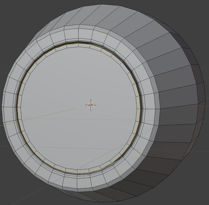
- Position the mouse in the 3D Viewport window. Press Ctrl + B and press Enter
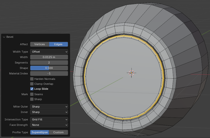
- In the Bevel window, change the following values:
Width:    0.0125
Segments: 2
- On the top bar, click the Face button
- Click the large central face to select it
- Press E to extrude
- Then press S to resize, then press Enter
- In the Extrude Region and Move window, change the X and Y values as follows:
Scale X: 0.65
      Z: 0.65
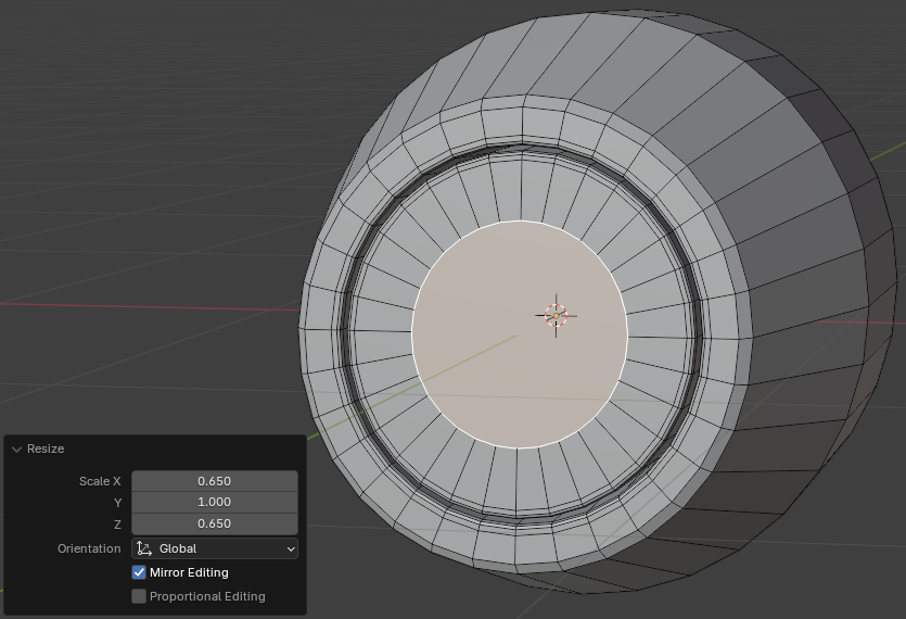
- Position the mouse in the 3D Viewport window. Press G to move the face
- Move the mouse slightly and click
- In the Move window, change the following values:
Move X: 0
          Y: 0
          Z: -0.105
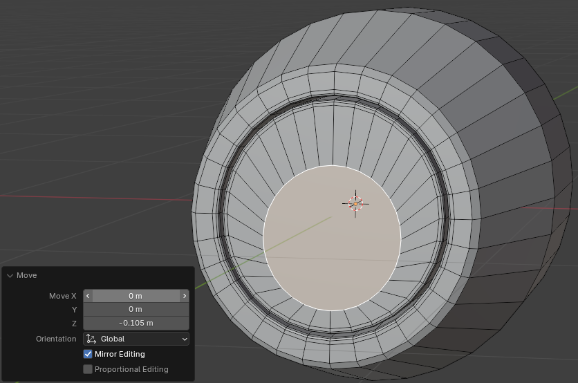
- While the face is still selected, press E to extrude
- Then press S, then press Enter
- In the Extrude Region and Move window, change the following values:
Move X: 0.975
     Z: 0.975
- While the face is still selected, press E to extrude
- Tthen press S, then press Enter
- In the Extrude Region and Move window, change the following values:
Move X: 0.975
     Z: 0.975
- While the face is still selected, press E to extrude
- Then press S, then press Enter
- In the Extrude Region and Move window, change the following values:
Move X: 0.205
     Z: 0.85
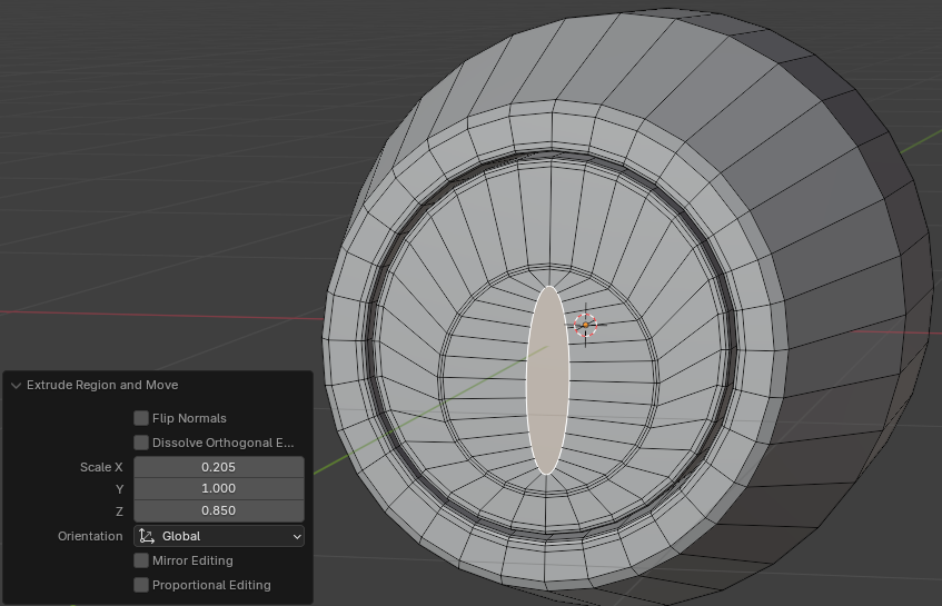
- On the top tool menu, click the Edge button
- Press and hold Alt
- Release Alt
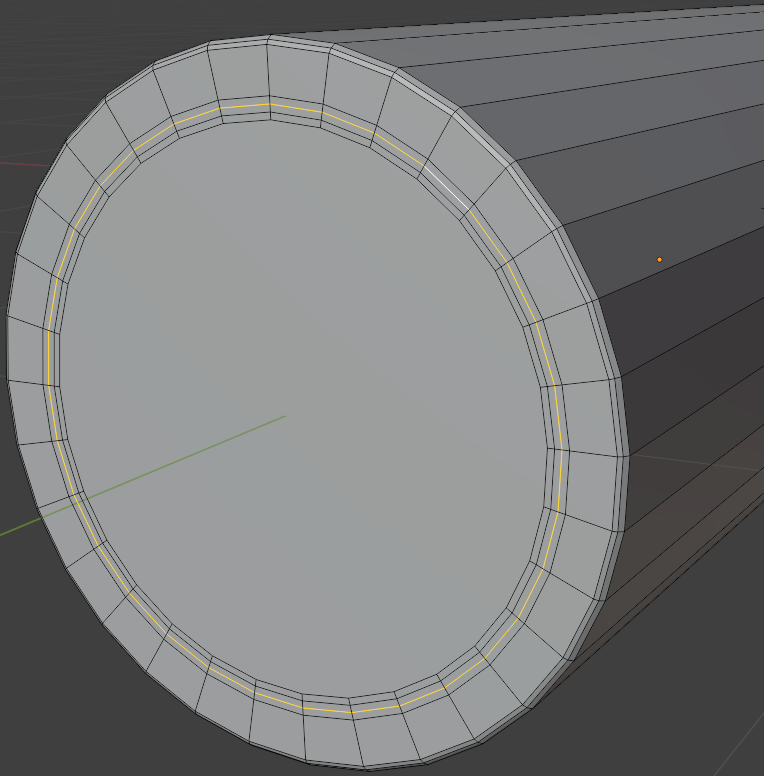
- Press G slightly and click
- In the Move window, change the values as follows:
Move: X: 0
       Y: 0.025
       Z: 0
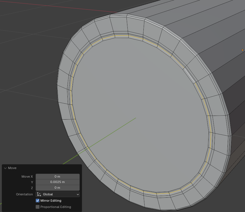
- On the top toolbar, click the Face button
- Click the large oval face on the lock to select it
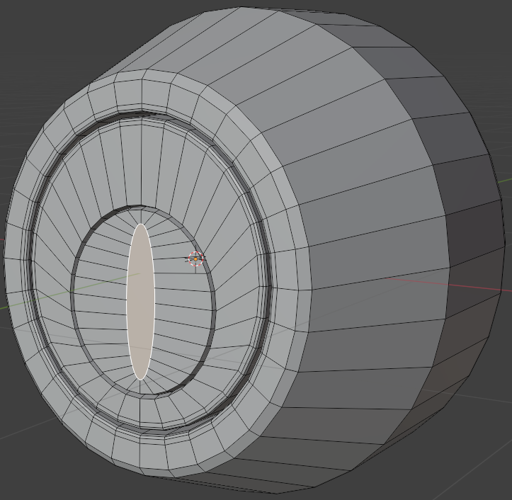
- Press E to extrude and press Enter
- In the Extrude Region and Move window, change the following values:
Move X:  0
     Y:  0
     Z: -0.75
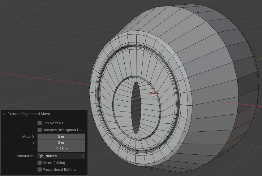
- To save the lock, on the main menu, click File -> Save
- Click Save
- While the lock is still selected, in the Properties window, click the Modifiers button

- In the Properties window, set the Levels Viewport to 2:
Levels Viewport: 2
- Right-click the lock and click Shade Smooth:
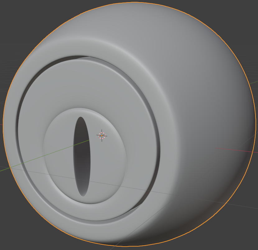
- To save, on the main menu, click File -> Save As...
- Set the document name Door-Lock-Simple-2
Adding Windows
Obviously, a house should have walls and window. In this section, we will add them to the model.
Finalizing the Interior Door
Practical Learning: Finalizing the Interior Door
- Click the default cube to select it (it should be selected already)
- In the Properties window, click the Object button (it should be selected already) to access the primary properties of the cube
